Motor drive unit

a motor drive and motor technology, applied in the direction of locomotives, multiple dynamo-motor starters, dynamo-electric converter control, etc., can solve the problems of large motor current detection error, difficulty in wide range of vector control or estimation of rotor position by current detection, etc., to improve the accuracy of current detection, eliminate switching noise interference, and low cost

Inactive Publication Date: 2007-01-18
PANASONIC CORP
View PDF13 Cites 42 Cited by
  • Summary
  • Abstract
  • Description
  • Claims
  • Application Information

AI Technical Summary

Benefits of technology

[0004] The motor drive unit according to the present invention comprises a DC power source, a plurality of inverter circuits for converting DC power of this DC power source to AC power, a current detector for detecting an output current of at least one of those plurality of inverter circuits, and a controller for performing PWM control of those plurality of inverter circuits. This controller is constructed in a way to synchronize a PWM period of the plurality of inverter circuits, so as to drive a plurality of motors at once by means of those plurality of inverter circuits respectively. By virtue of this configuration, it becomes possible to detect the current during an ON period or OFF period when no switching noise of any transistor in a plurality of inverter circuits is produced, and this enables to eliminate switching noise interference during a detection of current, improve the accuracy of detection of current, and thus realize a motor drive unit of low cost, high performance and high efficiency. Furthermore, it also enables to perform detection of current with an inexpensive shunt resistors system, and estimate a rotor position by detection of current accurately, to provide a highly reliable motor drive unit.

Problems solved by technology

This motor drive unit of conventional system, in which the period of pulse width modulation (hereinafter abbreviated as PWM) of a plurality of inverter circuits is controlled independently of one another and the motor current detecting timings are different, had such problems as large motor current detecting error due to switching noise of the inverter circuits, difficulty of a wide range of vector control or of estimation of rotor position by detection of current.

Method used


Image

  • Motor drive unit
  • Motor drive unit
  • Motor drive unit

Examples


embodiment 1

Preferred Embodiment 1

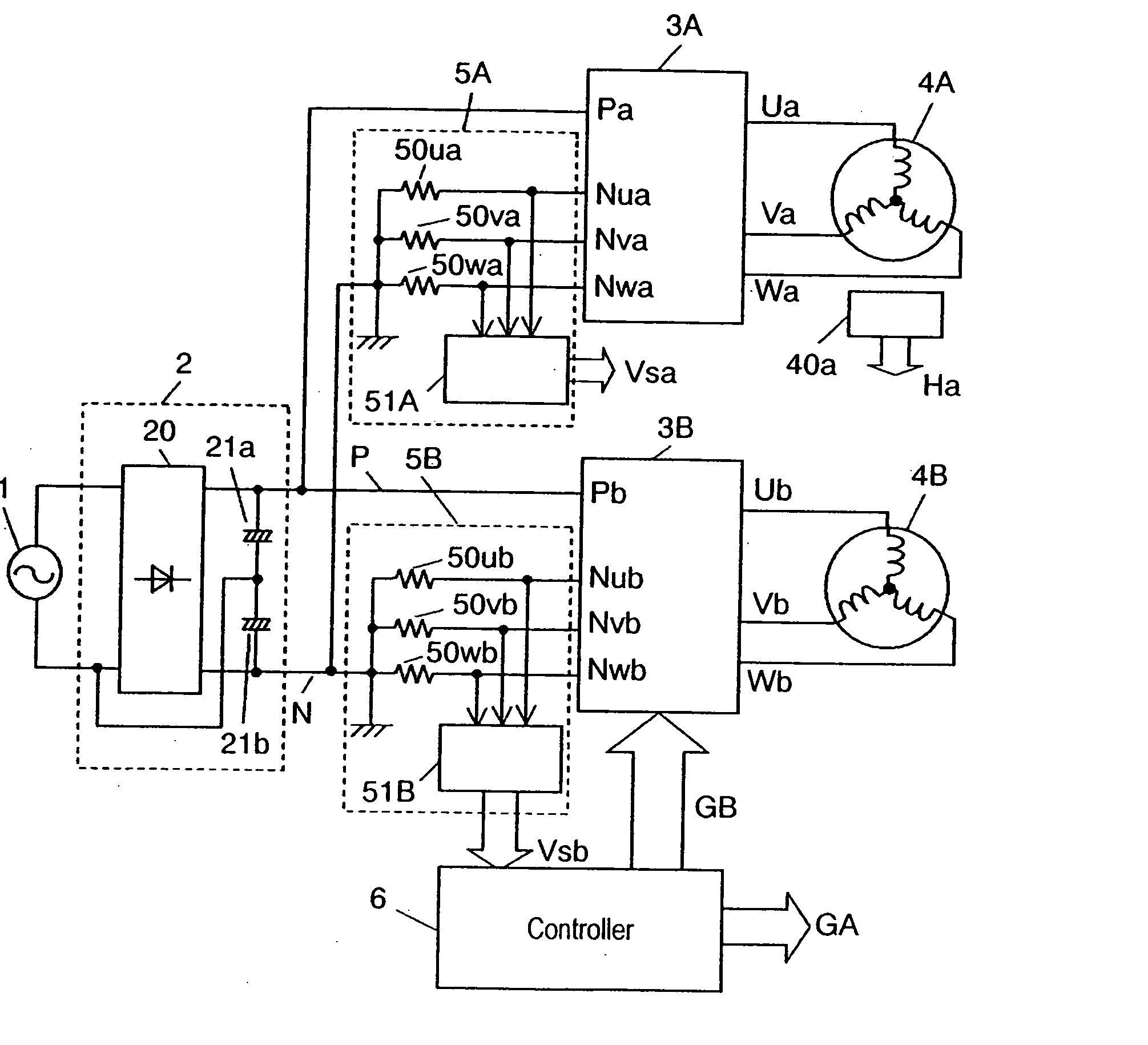
[0018]FIG. 1 indicates a block diagram of the motor drive unit in the preferred embodiment 1 of the present invention. In FIG. 1, AC power is applied from AC power source 1 to DC power source 2 constituted of full-wave rectification circuit 20 and electrolytic capacitors 21a, 21b for conversion into DC power, and the DC power is converted by inverter circuits 3A, 3B into 3-phase AC power to drive motors 4A, 4B. Current detectors 5A, 5B are connected to the negative voltage terminal side of inverter circuits 3A, 3B for detecting the electric current flowing through the respective 3-phase lower arms of inverter circuits 3A, 3B, to thereby detect the output current of inverter circuits 3A, 3B, i.e. electric current in the respective phases of motors 4A, 4B.

[0019] Controller 6, composed of a high-speed processor such as microcomputer having a plurality of PWM controllers for performing PWM control of inverter circuits 3A, 3B, or digital signal processor (abbreviat...

embodiment 2

Preferred Embodiment 2

[0038]FIG. 6 indicates a timing chart of PWM period and current detection timing of the respective inverter circuits in the preferred embodiment 2, and FIG. 7 shows a flow chart for performing detection of current and vector operation alternately with carrier signals by synchronizing the PWM control of inverter circuits to be driven at once. In FIG. 6 and FIG. 7, first inverter circuit 3A and second inverter circuit 3B are identical in PWM period, and perform timing of detection of current by current detectors 5A, 5B alternately. Other configuration is the same as that in the first preferred embodiment and, therefore, explanation on it will be omitted by putting the same reference numbers.

[0039] Here, explanation will be made, by using FIG. 7, on the flow of performing detection of current and vector operation alternately with carrier signals by synchronizing the PWM control of inverter circuits to be driven at once.

[0040] In FIG. 7, a carrier signal interrup...

embodiment 3

Preferred Embodiment 3

[0044]FIG. 8 indicates a timing chart of PWM period and current detection timing of the respective inverter circuits in the third preferred embodiment. FIG. 8 shows a timing of detection of current in the case where first inverter circuit 3A and second inverter circuit 3B are identical in PWM period, and that their PWM periods are shifted by 180 degree from each other. Other configuration is the same as that in the first preferred embodiment and, therefore, explanation on it will be omitted by putting the same reference numbers.

[0045] By equalizing the count-up time and the count-down time of triangular wave carrier signals, it becomes possible to realize a phase shift of 180 degree easily, enabling PWM control with 180 degree phase shift. During continuity of the lower arm transistor of first inverter circuit 3A (Gna high), continuity is established in the upper arm transistor of second inverter circuit 3B (Gpb high), while, during continuity of the lower arm...


PUM


Abstract

A motor drive unit comprises a DC power source, a plurality of inverter circuits for converting the a power of this DC power source to an AC power, current detectors for detecting an output current of at least one of those plurality of inverter circuits and a controller for performing PWM control of those plurality of inverter circuits. This controller is constructed in a way to synchronize a PWM period of the plurality of inverter circuits, so as to drive a plurality of motors at once by means of those plurality of inverter circuits respectively.

Description

FIELD OF THE INVENTION [0001] The present invention relates to a motor drive unit for driving a plurality of motors at once by means of a plurality of inverter circuits. BACKGROUND OF THE INVENTION [0002] Conventionally, in this type of motor drive unit for driving a plurality of motors at once, it was a normal practice to control a plurality of inverter circuits and a plurality of motors separately from one another. For example, such unit is disclosed in Japanese Laid-Open Patent Application No. 2002-165476. [0003] This motor drive unit of conventional system, in which the period of pulse width modulation (hereinafter abbreviated as PWM) of a plurality of inverter circuits is controlled independently of one another and the motor current detecting timings are different, had such problems as large motor current detecting error due to switching noise of the inverter circuits, difficulty of a wide range of vector control or of estimation of rotor position by detection of current. SUMMA...

Claims


Application Information

Patent Timeline
Patent Type & Authority Applications(United States)
IPC IPC(8): H02P1/54H02P5/74
CPCH02P5/74H02P21/06H02P5/747
Inventor KIUCHI, MITSUYUKITAMAE, SADAYUKIHAGIWARA, HISASHISUZUKI, MASAHIROKOJIMA, SHUICHI
Owner PANASONIC CORP
Why Eureka
Try Eureka