
Magnetic screening system

a screening system and magnetic technology, applied in the direction of magnetic property measurement, material magnetic variables, instruments, etc., can solve the problems of low passthrough rate, low detection efficiency, and low passthrough rate of one to two hundred persons per hour, so as to increase the automation of detection, identification or classification processes and increase the processing rate of peopl

Inactive Publication Date: 2007-01-18
ASSURANCE TECH CORP
View PDF10 Cites 19 Cited by
  • Summary
  • Abstract
  • Description
  • Claims
  • Application Information

AI Technical Summary

Benefits of technology

The system significantly increases the processing rate of individuals through magnetic screening systems to 600-700 per hour, reduces false detections, and allows for the detection of ferromagnetic objects without the need to remove them, while being safe for individuals with medical devices.

Problems solved by technology

Although people have become accustomed to passing through portal metal detectors, the process remains relatively slow for a number of reasons.
Another reason for the slow process is due to false detection or detection of non-weapon metals, such as wrist watches, belt buckles, metallic wires found in ordinary garments, personal adornments such as broaches or hair clips, and loose coins in pockets.
Typically, all of the delays result in a passthrough rate of between one and two hundred persons per hour.
To accommodate large crowds, many portal metal detectors are operated in parallel, which leads to staffing, training, and machine calibration issues.
When a person in a wheelchair passes through the portal metal detector, the portal metal detector is overwhelmed by the metal content of the wheelchair and unable to detect relatively small metal objects on the person.
In addition, even if the wheelchair is not passing through the portal metal detector, it can influence the detector to such an extent that the detector makes erroneous readings.
Active detectors can be dangerous for people using medical devices, such as pacemakers, that are sensitive to electro-magnetic fields.

Method used


Image

  • Magnetic screening system
  • Magnetic screening system
  • Magnetic screening system

Examples


Embodiment Construction

[0043] A description of preferred embodiments of the invention follows.

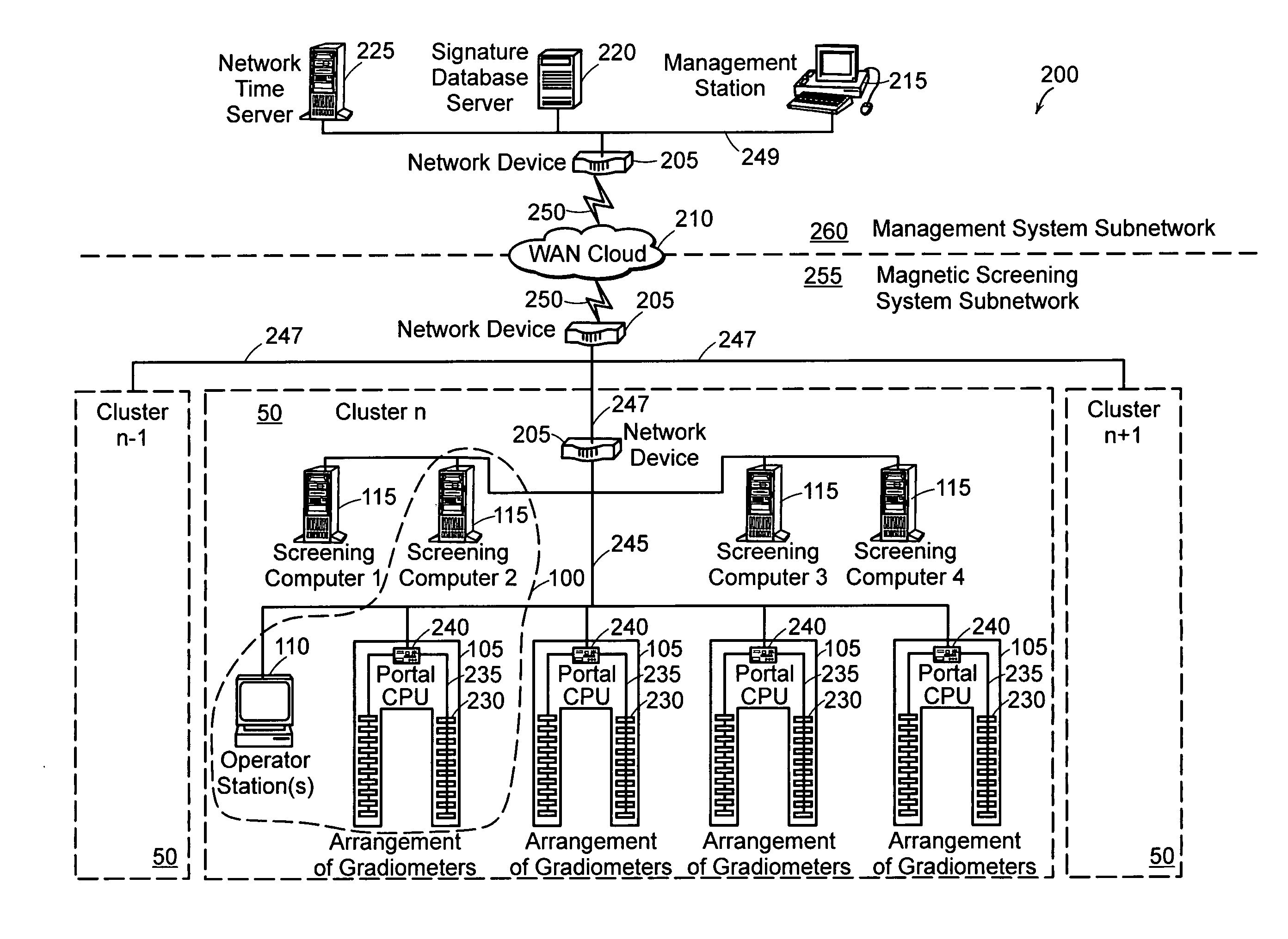
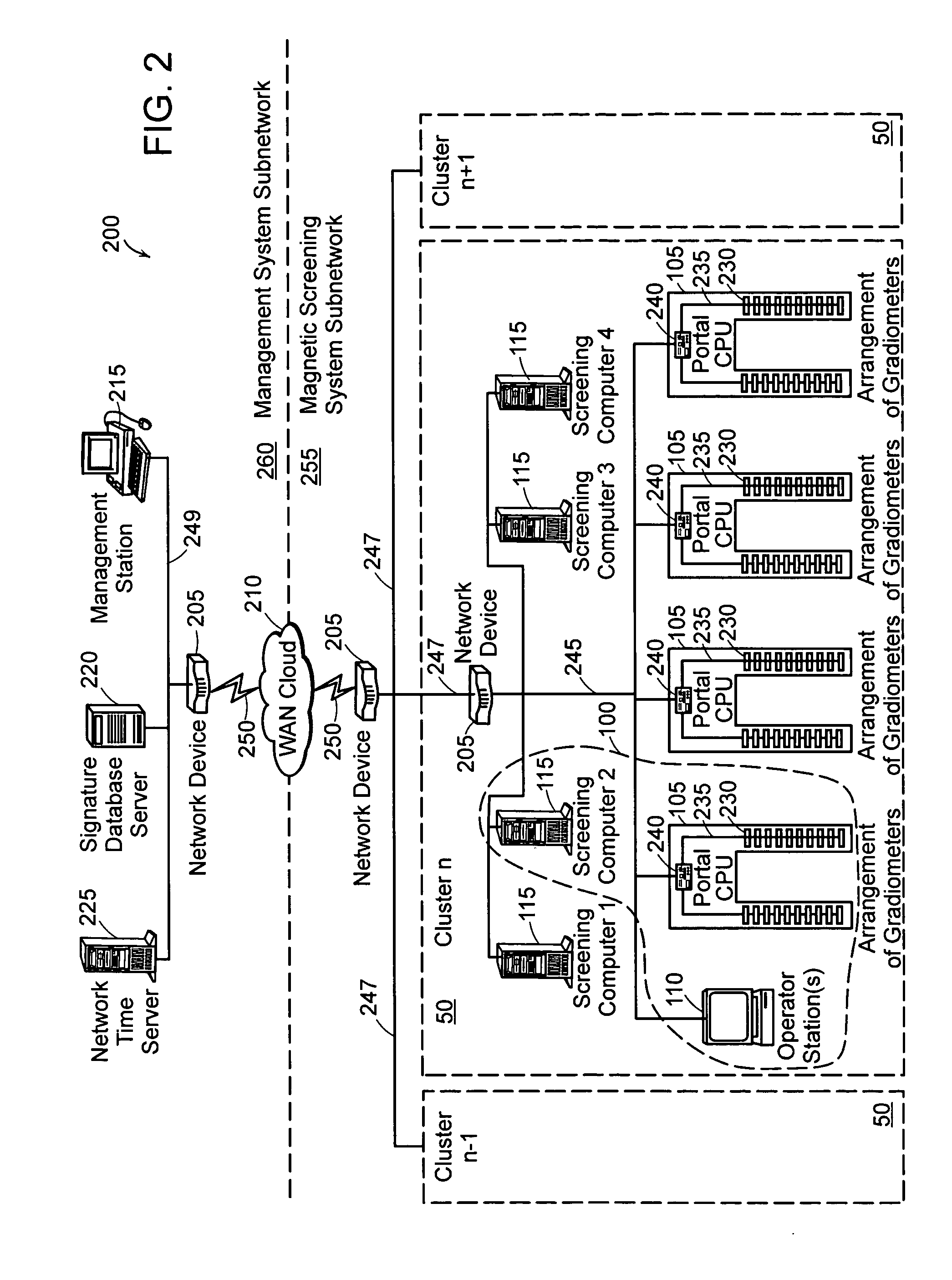
[0044] The principles of the present invention may be employed at multiple levels in the magnetic screening system 100 and a network of magnetic screening systems 100 each including multiple gradiometers. The multiple levels include at least a network level, system level, mode of operation level, and gradiometer design level. A brief overview of each is presented, and details of each, in turn, follows the brief overview.

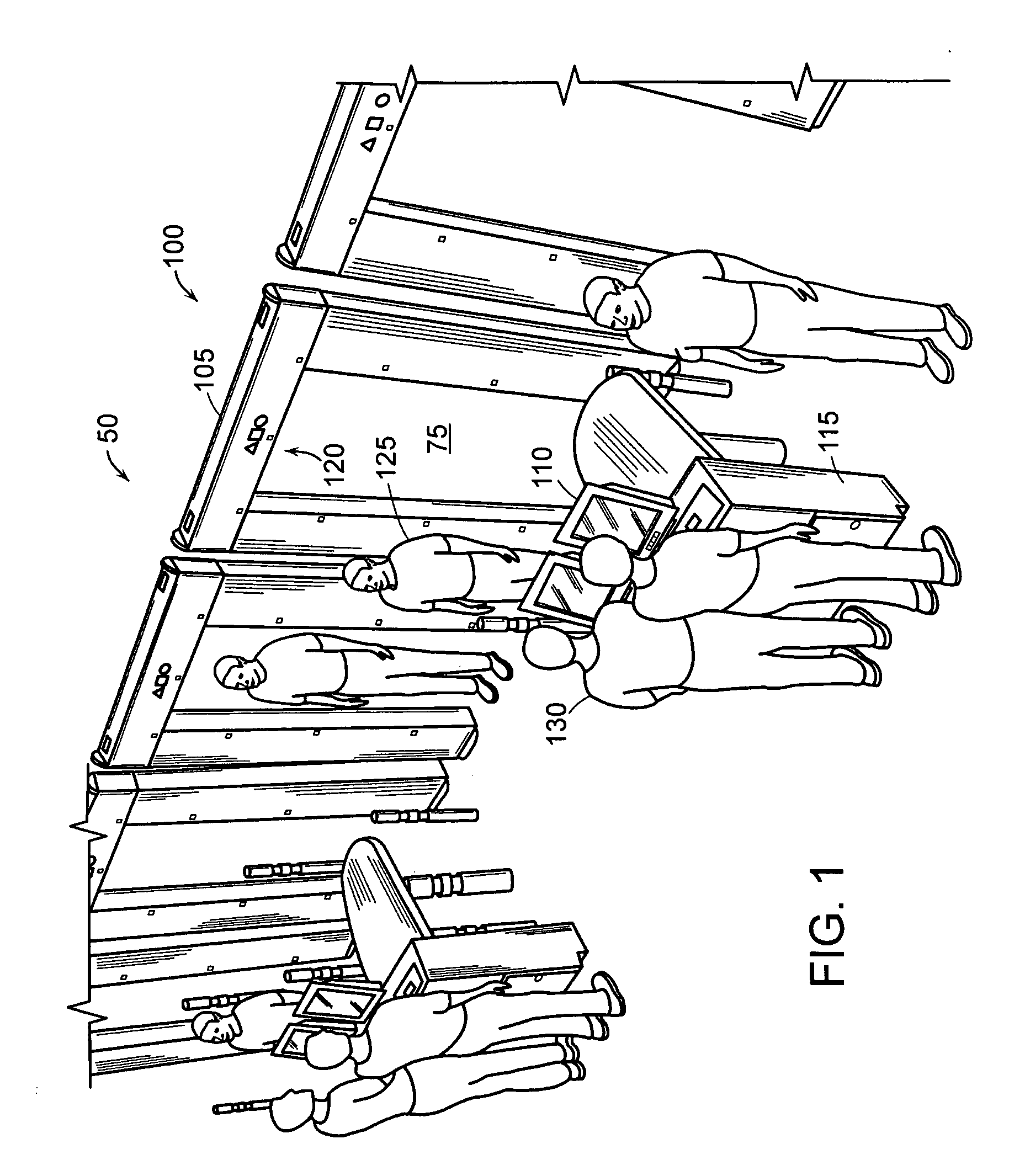
[0045]FIG. 1 is a pictorial diagram of a cluster 50 of magnetic screening systems 100, each using gradiometers configured in a portal 105. Magnetic screening systems 100 are typically used at an entrance to a public place, such as an airport, government building, public school, or amusement park. The magnetic screening systems 100 are used to ensure safety for the public. The magnetic screening systems can identify magnetic objects, referred to herein as “target objects” on a person, as understo...


PUM


Abstract

A magnetic screening system uses directional gradiometers with high resolution and accuracy to measure magnetic field signatures of target objects (e.g., gun, knife, cell phone, keys) in a volume of interest. The measured signatures can be compared to signatures of known objects stored in a local database. Various mathematical processes may be used to identify or classify target object signatures. In a network of magnetic screening systems, the magnetic screening systems can transmit signatures to a central signature database, and a management computer can share the central signature database with all of the magnetic screening systems on the network. The magnetic screening system can operate in multiple modes, such as a tracking mode, measurement mode, and self-test mode. Through use of unique processes and designs, the magnetic screening system can achieve a high rate of processing persons for target objects.

Description

RELATED APPLICATIONS [0001] This application is a continuation of U.S. application Ser. No. 11 / 073,424, filed Mar. 4, 2005. The entire teachings of the above application are incorporated herein by reference.BACKGROUND OF THE INVENTION [0002] In recent years, screening for weapons at entrances of public places, such as airports, government buildings, public schools, and amusement parks, has increased to ensure safety for the public at those places. Screening for weapons can include requiring people entering such public places to pass through a magnetic screening system such as a portal metal detector. Although people have become accustomed to passing through portal metal detectors, the process remains relatively slow for a number of reasons. [0003] One reason for the slow process is that people must empty their pockets of all metallic objects, remove their coats, and sometimes remove their shoes. The objects and clothing are either physically inspected by hand or passed through an x-...

Claims


Application Information

Patent Timeline
Patent Type & Authority Applications(United States)
IPC IPC(8): G01R33/02
CPCG01V3/081
Inventor MURRAY, PAUL D.PALECKI, LOUIS S.PLACE, WILLIAM C.
Owner ASSURANCE TECH CORP
Learn More