
Medical tracking system with infrared data transfer

a tracking system and infrared technology, applied in the field of medical tracking systems and data transfer, can solve the problems of impairing control function, superimposing infrared tracking signals on control signals, etc., and achieve the effect of minimizing or eliminating disruptions, control signals

Inactive Publication Date: 2007-01-18
BRAINLAB
View PDF30 Cites 7 Cited by
  • Summary
  • Abstract
  • Description
  • Claims
  • Application Information

AI Technical Summary

Benefits of technology

[0006] The invention provides a combined system including a medical tracking system that comprises a camera array and an infrared light source, and at least one appliance that is used in a medical setting (e.g., in a treatment and / or examination room and / or setting), in particular a medical appliance. The medical appliance can be controlled using infrared signals and / or can exchange data by means of infrared signals, wherein the infrared light source of the medical tracking system forms at least a part of the system's wireless control unit and / or data exchange unit. In other words, the infrared light source of the medical tracking system can act as a carrier for data signals so as to enable data exchange between the tracking system and the medical appliances. This is advantageous, for example, in that the infrared light source no longer operates as a disrupting factor but rather as a part of the control / data transfer system, and disruptions can therefore be minimized or eliminated. Further, control signals and / or data transfers can be made more secure and more reliable, since the infrared light source of the tracking system is relatively intense. Other advantages are also described below.
[0034] In accordance with a preferred embodiment of the method, the camera array is controlled such that recording is disabled at times when there are no tracking signal outputs. This avoids the undesired use of control signals or data exchange signals for instrument tracking.
[0038] A central control system overcomes the practical problem of having to provide multiple infrared control units in the operating theater to control different devices. Multiple remote controls are no longer needed, and necessary settings can be made to the appliances from the central control unit (e.g., the touch-sensitive screen).
[0039] Problems with an interrupted “line of sight”, e.g., with offset control paths, as may occur using manual remote controls are eliminated, since the infrared flashes of the tracking system are intense enough to reach substantially every angle in the operation theater, either directly or via sufficiently intense light reflections in the room. As a result, remote controls for the appliances are no longer needed, nor are the batteries used in such remote control devices. Omitting the remote controls and their batteries also makes it much easier to maintain sterility in the operating theater.
[0040] The invention enables wireless data transfer to multiple receivers without disruptive cables in the operating theater and with very low integration costs since at least the transmitter, i.e., the infrared light source, is already available. Multiple appliances can be completely integrated in the operating theater without multiple interfaces.

Problems solved by technology

In operating theaters provided with an infrared tracking system that operates using very intense infrared signals, however, the infrared tracking signals can be superimposed on the control signals of the remote controls and impair the control function.

Method used


Image

  • Medical tracking system with infrared data transfer
  • Medical tracking system with infrared data transfer

Examples


Embodiment Construction

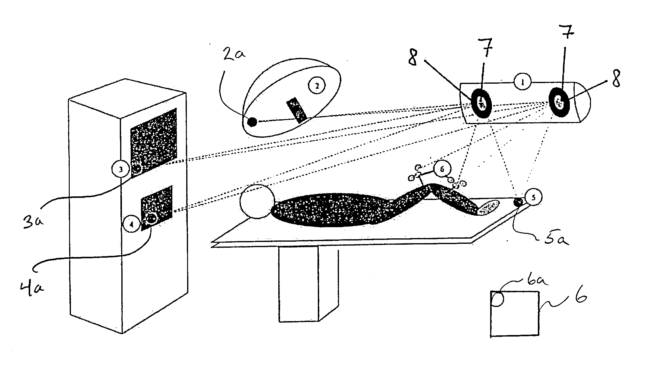
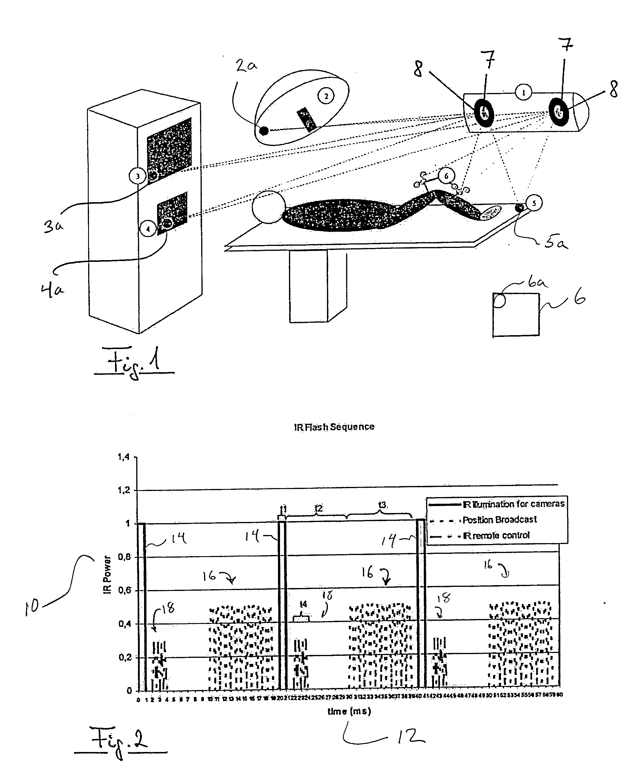
[0044]FIG. 1 illustrates a medical tracking system 1 that includes two infrared cameras 7 which are surrounded by diode rings 8. The diode rings 8 contain infrared diodes and can emit infrared flashes and / or signals, the reflections of which can be received by the cameras 7 (infrared cameras). In this way, the position of a patient's body part, for example, is conventionally “tracked”, i.e., determined and tracked. This conventional tracking, for example, is performed using reference stars 6 that are attached to the patient, such as the patient's leg. Medical instruments or treatment means also can be tracked using such reference stars 6.

[0045] Other appliances also are shown in the operating theater setup of FIG. 1, namely a patient couch 5, an operation lamp 2, a navigation system 3 and a recording device (e.g., video / audio) 4. Additional appliances 6, such as a medical robot, data or image recording and / or reproducing appliance, microscope, surgical instrument, endoscope, ultras...


PUM


Abstract

A medical tracking and appliance control system includes a medical tracking system having a camera array and an infrared light source, and at least one medical appliance controllable via infrared signals or operative to exchange data via infrared signals. The infrared light source of the medical tracking system is operable to provide wireless control and / or data exchange with the medical appliance.

Description

RELATED APPLICATION DATA [0001] This application claims priority of U.S. Provisional Application No. 60 / 695,179 filed on Jun. 29, 2005, which is incorporated herein by reference in its entirety.FIELD OF THE INVENTION [0002] The invention relates to the field of medical tracking systems and data transfer between medical appliances. BACKGROUND OF THE INVENTION [0003] Medical tracking systems are used to track and / or determine the three-dimensional position of instruments or treatment means in a medical work space. In most cases, medical tracking systems comprise two cameras, and such systems may operate using non-visible light, e.g., using infrared light cameras that detect infrared light. The infrared light may be provided by a system-integrated infrared light source, in most cases in the form of short flashes of infrared light. These flashes are reflected by reference reflector means on instruments, patients or treatment means, from which the three-dimensional position of the instru...

Claims


Application Information

Patent Timeline
Patent Type & Authority Applications(United States)
IPC IPC(8): H04N5/228H04N23/40
CPCA61B18/14A61B19/2203A61B19/52A61B2019/5255A61B19/5223A61B19/5244A61B2017/00212A61B19/5202A61B90/36A61B2034/2055A61B34/20A61B90/30A61B34/30A61B90/20
Inventor GOLDBACH, GUNTER
Owner BRAINLAB
Learn More