Lighting unit and liquid crystal display device using the lighting unit

Active Publication Date: 2007-01-18
GOLD CHARM LTD
View PDF11 Cites 26 Cited by
  • Summary
  • Abstract
  • Description
  • Claims
  • Application Information

AI Technical Summary

Benefits of technology

[0021] With the lighting units according to the invention and the LCD devices using them, it is possible to achieve reduced size and weight, and to generate rays of light with less color un-uniformity by use of their relatively simple structures.
[0022] The diffusion materials dispersed in the light guide plate aid in mixing the colors represented by rays of light emitted from LED light sources. The diffusion materials are made of a material having optical characteristics, such as refractive index, which are different from those of a base material of the light guide plate. Incident rays of light

Problems solved by technology

That is because fluorescent lamps need peripheral circuits, such as inverter circuits, to turn on the lamps, and because the inverter circuits for the fluorescent lamps make noise.
As a result, the arrangement of LEDs causes high and low intensities of the ray of light.
In particular, this causes a problem in that the high and low intensities of the rays of light are

Method used


Image

  • Lighting unit and liquid crystal display device using the lighting unit
  • Lighting unit and liquid crystal display device using the lighting unit
  • Lighting unit and liquid crystal display device using the lighting unit

Examples


first embodiment

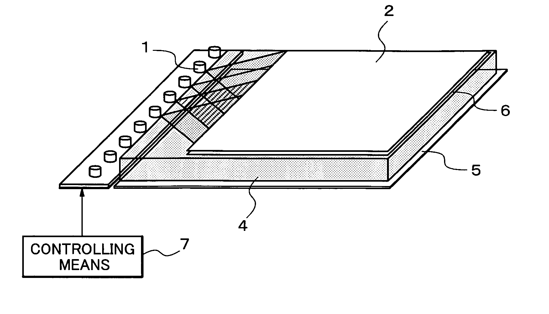
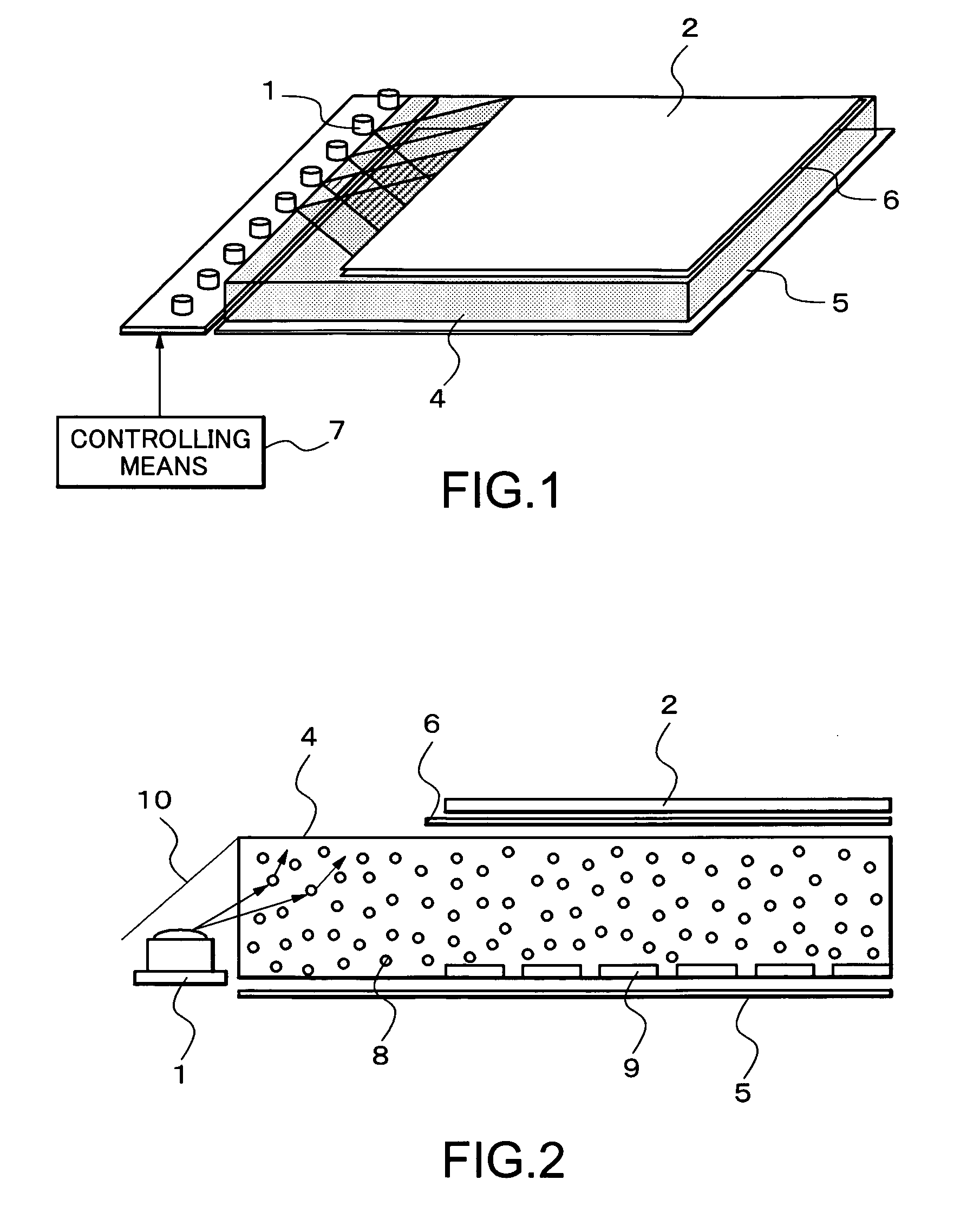
[0032] Descriptions will be provided for a lighting unit and a LCD device using the lighting unit according to the present invention with reference to FIGS. 1 to 4. As shown in FIGS. 1 and 2, the LCD device according to the embodiment are mainly composed of LED light sources 1 for red (R), green (G) and blue (B) colors, controlling means 7, a LCD panel 2, a light guide plate 4, a reflection plate 5, an optical sheet 6 and a reflector 10. The controlling means 7 controls brightness of each of the LED light sources 1. The reflector 10 makes the light emitted from each of the LED light sources 1 incident on the light guide plate 4. The light guide plate 4 mixes the three colors emitted from the LED light sources 1 and guides mixed light to the LCD panel 2. Reflection patterns 9 are arranged on a surface of the light guide plate 4, the surface being closer to the reflection plate 5. The reflection plate 5 reduces loss of light and increase light transmitted to the LCD panel 2. The refle...

fifth embodiment

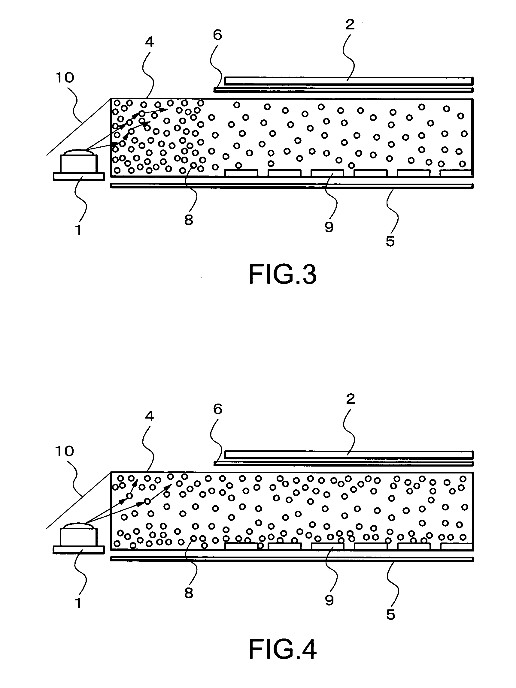
[0048] A fifth embodiment will now be described. In the above four embodiments, rays of light emitted from the LED light sources are diffused in various directions by the variously-configured diffusion materials and structures of those embodiments. As a result, the rays of light may leak out of the front surface and the rear surface of each of the guide members.

[0049] In the fifth embodiment, a sheet with a high reflectance can be adhered to any or all of the surfaces of the light guide plates shown in FIGS. 1 to 5. For example, a metallic film with a high reflectance can be formed on any one or more of the surfaces of the light guide plates shown in FIGS. 1 to 5 by means of deposition or the like.

[0050] Such a configuration makes it possible to realize a LCD device with the following features. The sheet with a high reflectance allow to reflect rays toward a different direction from the LCD panel and reduce loss of rays of light. Brightness efficiency is improved. In addition, colo...


PUM


Abstract

In a liquid crystal display device using LEDs emitting a plurality of colors as the light sources, diffusion materials are dispersed in a light guide plate. The light guide plate is used to guide and mix the plurality of colors with one another. The diffusion materials are made of a material having optical characteristics, such as a refractive index, different from those of a base material of the light guide plate.

Description

BACKGROUND OF THE INVENTION [0001] 1. Field of the Invention The present invention relates to a lighting unit and a liquid crystal display device using the lighting unit, and more particularly relates to a structure of a light guide plate used in the lighting unit. [0002] 2. Description of Related Art [0003] Liquid crystal display (LCD) devices have several features, such as thinness, lightweight and low power consumption. Because of these features, LCD devices are widely used in fields including Office Automation (OA) machines, Audio and Visual (AV) appliances and cell phone terminal devices. In case of transmissive LCD devices, the display includes a backlight to irradiate a rear surface of the LCD panel. The LCD device indicates information by controlling the amount of transmitting rays of light emitted from the backlight light sources. Fluorescent lamps have been used as the backlight light sources. In recent years, however, light-emitting diodes (LEDs) are used instead of the f...

Claims


Application Information

Patent Timeline
IPC IPC(8): F21V9/00
CPCG02B6/0018G02B6/0068G02B6/0041G02B6/0028G02F1/1335
Inventor ITAYA, HIDEKI
Owner GOLD CHARM LTD
Why Eureka
Try Eureka