Virtual resolution enhancement in diagnostic imaging using FEA

a virtual resolution and diagnostic imaging technology, applied in the field of virtual resolution enhancement of diagnostic imaging using fea, can solve the problems of physical limitations of non-invasive imaging, the clinician's problem of physical limitations, and the patient's energy must be transmitted to the patient, so as to reduce the cost, the effect of reducing the cost and reducing the cost of imaging

Inactive Publication Date: 2007-01-18
PALMER MARK L
View PDF0 Cites 16 Cited by
  • Summary
  • Abstract
  • Description
  • Claims
  • Application Information

AI Technical Summary

Benefits of technology

[0013] Another embodiment uses a prototype model as the high level model. The prototype would be morphed (for example see Sermesant, et al., 2003) to fit the patient anatomy based on a set of parameters measured from the patient. An example is the use of two dimensional ultrasound to measure landmarks on an anatomical structure and then morphing the prototype model of the anatomical structure to fit the patient. This embodiment has the potential to reduce the cost in the clinical setting since a cheaper imaging modality may be used at the time the patient is evaluated. The boundary conditions necessary for the analysis step may also be determined using an imaging modality that is lower cost or more readily available than MRI or CT.
[0014] Still another embodiment uses an archive of images or models. The patient history and physical parameters such as height, weight, gender, age, race or other demographic information are used to sel

Problems solved by technology

This limitation exists because in order to obtain an image, energy must be transmitted to the patient.
However, taking into account the limitations of allowable dosage range for x-ray radiation to a patient, CT scans are approximately 80% of the way to the theoretical physical limit on the order of 0.5 millimeters (1 millimeter=10−3 meters).
Therefore while rapid improvements are made in the rate and manner that C

Method used


Image

  • Virtual resolution enhancement in diagnostic imaging using FEA
  • Virtual resolution enhancement in diagnostic imaging using FEA
  • Virtual resolution enhancement in diagnostic imaging using FEA

Examples


Embodiment Construction

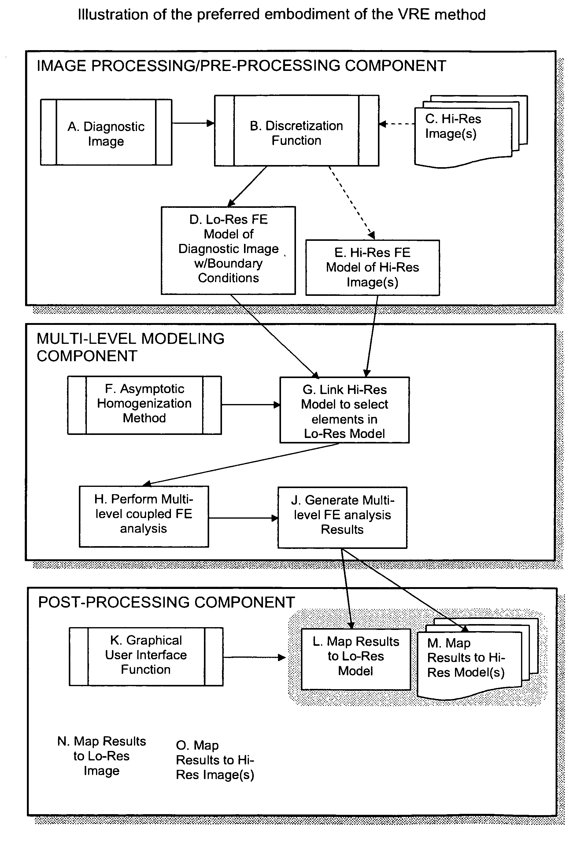
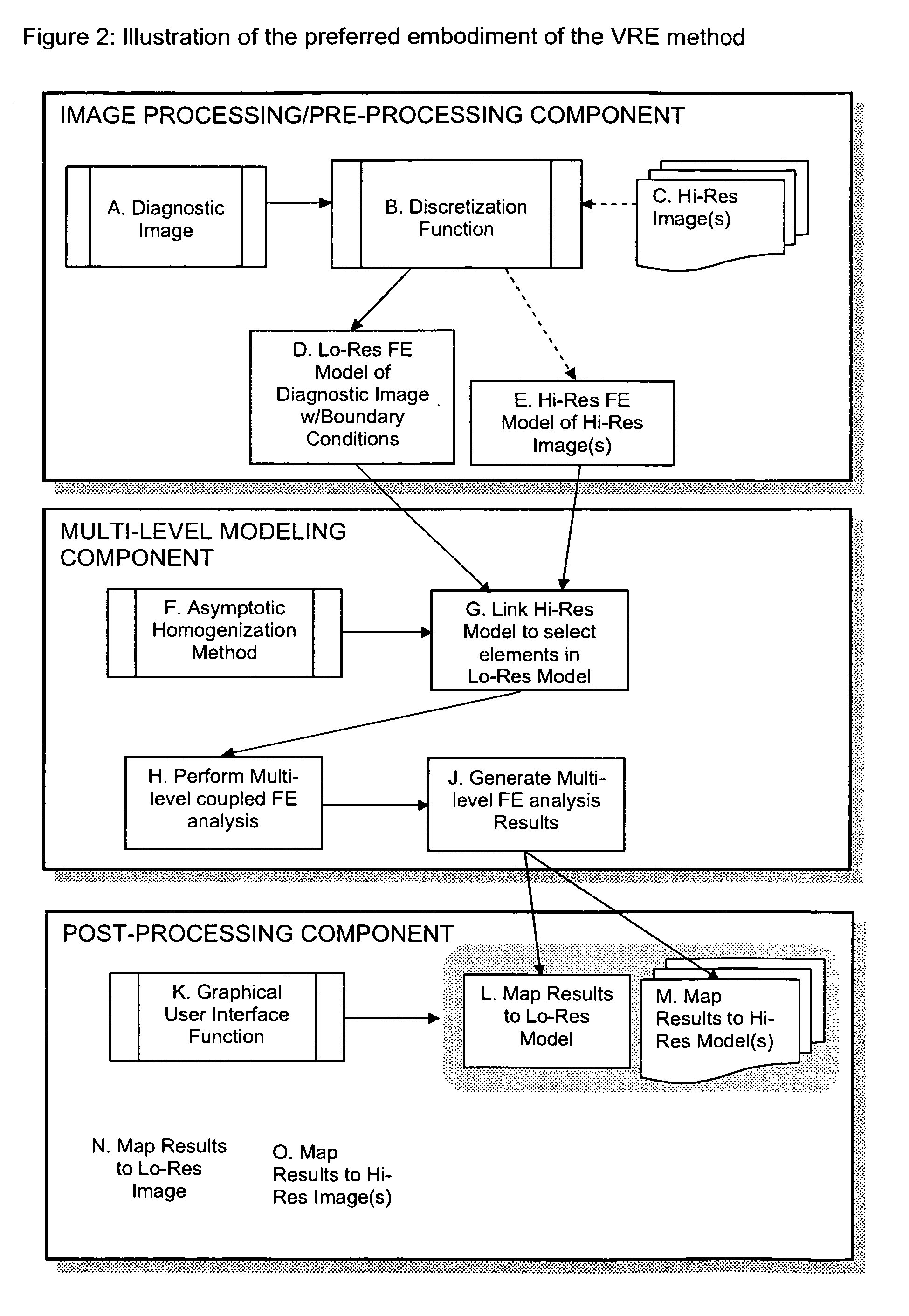
[0028] The present invention comprises a method for achieving resolutions higher than those available in a given imaging system by linking via mathematical modeling the image obtained from one imaging modality or setting to higher resolution images obtained in a different modality or setting thereby providing the user with information that would be difficult to visualize or obtain from the original image.

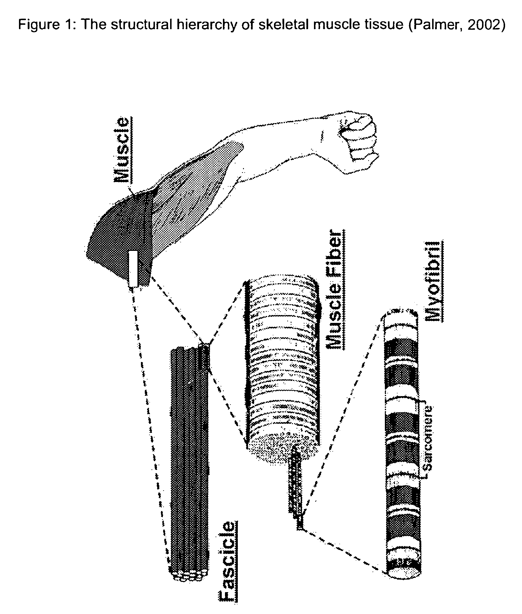
[0029] The present invention is predicated on the fact that the information that is present in a given image or sequence of images is may be difficult to interpret with the naked simply by viewing the image, zooming in on the image, or through processing of that image to highlight certain features. In addition, the information contained in the image may be related to other variables that are important to interpreting the image but in a way that may not be obvious even to a person experienced in reading or interpreting the images. This is particularly true in a biological setting be...


PUM


Abstract

A method is described for achieving resolutions beyond the resolution of a diagnostic imaging using multilevel computational analysis. This is accomplished by coupling the diagnostic image with images obtained at higher resolutions or with physiological models constructed at size scales beyond the resolution of the original diagnostic image. Using a discretization function, the image data or models are converted or generated so that they can be processed by a multilevel computational analysis function. The multilevel analysis then mathematically couples the models across two or more length scales generating parameters of interest at each level of analysis. A post-processing function provides the interface for the user to view the parameters of interest in the model derived from the original diagnostic image and/or the image itself and then “zoom-in” to a region by accessing the higher resolution image and/or model associated with it and viewing the parameters of interest.

Description

CROSS-REFERENCE TO RELATED APPLICATIONS [0001] This is a continuing non-provisional patent application of co-pending U.S. Provisional Patent Application Ser. No. 60 / 680,076, entitled METHOD FOR ACHIEVING “VIRTUAL RESOLUTION ENHANCEMENT” OF A DIAGNOSTIC IMAGING MODALITY BY USING COUPLED FEA ANALYSES and filed on 12 May 2005 by Mark L. Palmer and Mark B. Willis, now abandoned, the disclosure of which is incorporated here by reference.BACKGROUND OF THE INVENTION [0002] The present invention relates to the field of diagnostic medical imaging and provides a method for achieving “virtual resolution enhancement” (VRE) using coupled multilevel analyses for the purpose “zooming in” on a diagnostic image. The invention describes linking established technologies to create new functionality that displays via a user interface, variables of interest in order to provide information beyond the native resolution of a diagnostic medical image. For the purposes of this discussion, diagnostic medical i...

Claims


Application Information

Patent Timeline
IPC IPC(8): G06K9/00
CPCG06T7/0012
Inventor PALMER, MARK
Owner PALMER MARK L
Why Eureka
Try Eureka