Ultrasonic diagnostic apparatus and ultrasonic image generating method

Inactive Publication Date: 2007-01-18
GE MEDICAL SYST GLOBAL TECH CO LLC
View PDF10 Cites 61 Cited by
  • Summary
  • Abstract
  • Description
  • Claims
  • Application Information

AI Technical Summary

Benefits of technology

[0006] It is therefore an object of the present invention to provide an ultrasonic diagnostic apparatus, an ultrasonic image g

Problems solved by technology

Meanwhile, the prior art referred to above is accompanied by a problem that it is difficult to draw a biopsy needle on an ultrasonic image as will be described below.
That is, the prior art has a problem in that there are many cases in which since the angle of an ultrasonic beam relative to the biopsy needle is not taken into consideration

Method used


Image

  • Ultrasonic diagnostic apparatus and ultrasonic image generating method
  • Ultrasonic diagnostic apparatus and ultrasonic image generating method
  • Ultrasonic diagnostic apparatus and ultrasonic image generating method

Examples


first embodiment

[0056] In the first embodiment shown below, the outline and features of the ultrasonic diagnostic apparatus according to the first embodiment, and the configuration of the ultrasonic diagnostic apparatus and the flow of processing thereof will be explained in order, and advantages obtained by the first embodiment will finally be explained.

[0057] Outline and Features (First Embodiment)

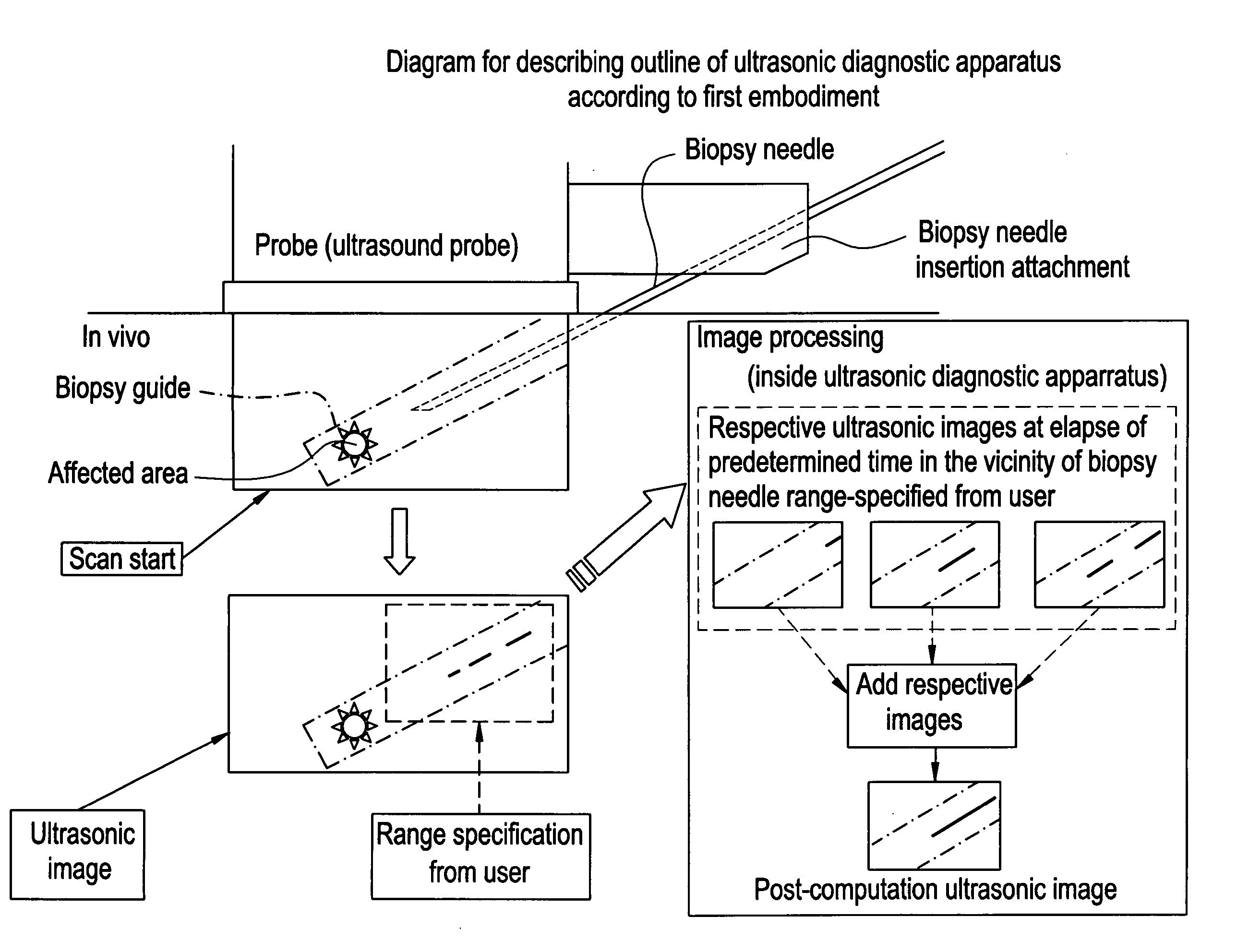
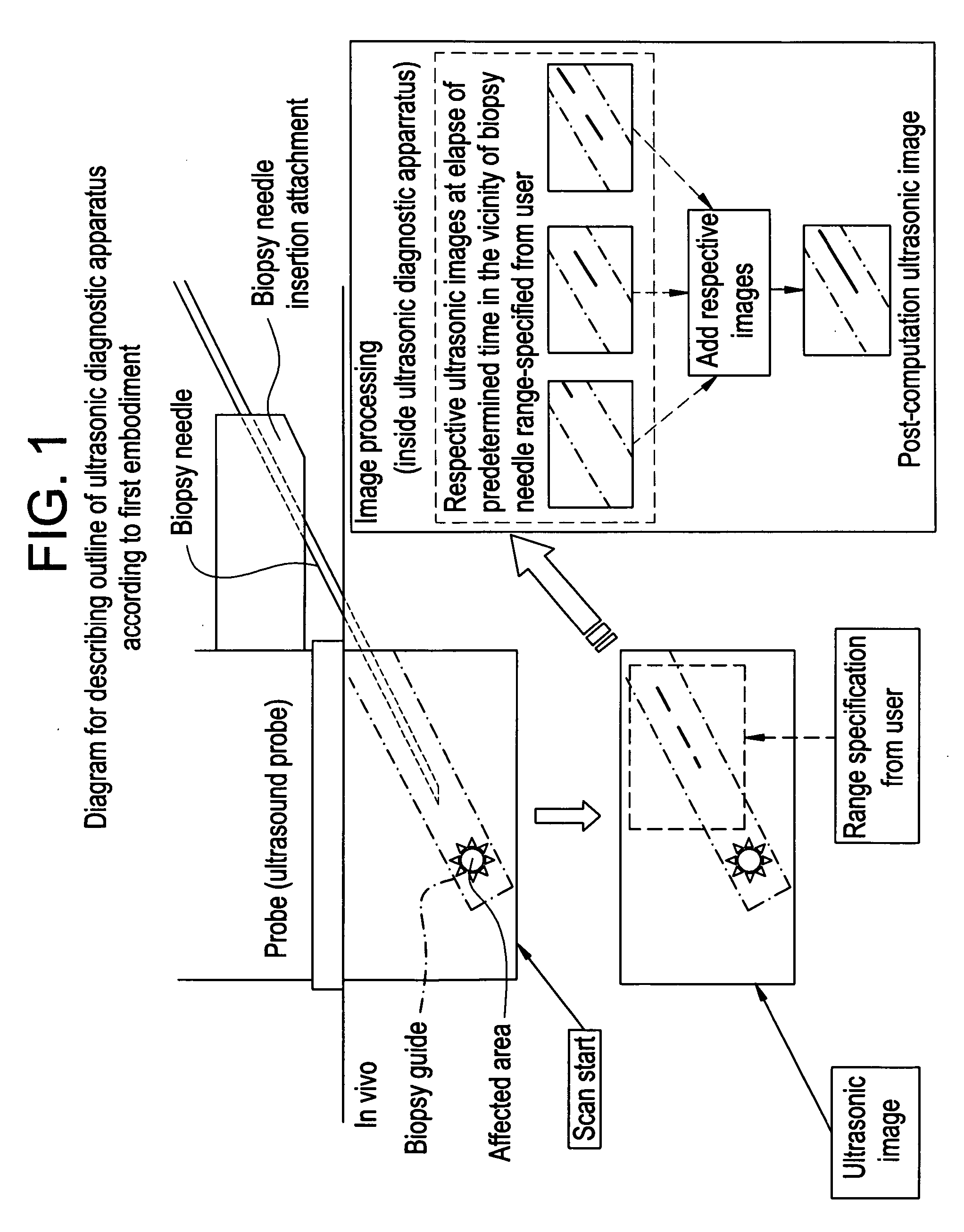
[0058] To begin with, the general outline and features of the ultrasonic diagnostic apparatus according to the first embodiment will be explained using FIG. 1. FIG. 1 is a diagram for describing the outline of the ultrasonic diagnostic apparatus according to the first embodiment. As shown in the same figure, the ultrasonic diagnostic apparatus brings a probe connected thereto into contact with a body surface to apply ultrasound, receives signals reflected from in vivo and a biopsy needle inserted into a body and generates ultrasonic images (tomograms) in the body and at the biopsy needle on the basis ...

second embodiment

[0083] Incidentally, although the first embodiment has explained the ultrasonic diagnostic apparatus which effects the image processing on the ultrasonic images near the biopsy needle, the present invention is not limited to it. The direction of radiation of the ultrasonic signal may be controlled so as to display the biopsy needle on the ultrasonic image.

[0084] Thus, in the second embodiment shown below, the outline and features of an ultrasonic diagnostic apparatus according to the second embodiment, and the configuration of the ultrasonic diagnostic apparatus and the flow of processing thereof will be explained in order, and advantages obtained by the second embodiment will finally be explained.

[0085] [Outline and Features]

[0086] To begin with, the general outline and features of the ultrasonic diagnostic apparatus according to the second embodiment will be explained using FIG. 5. FIG. 5 is a diagram for describing the outline of the ultrasonic diagnostic apparatus according to...

third embodiment

[0116] Now, although the ultrasonic diagnostic apparatuses according to the first and second embodiments have been explained so far, the present invention may be effected on various different forms even except for the first and second embodiments. Thus, various different forms will respectively be explained below in sorted forms of (1) through (9) as a third embodiment.

[0117] (1) Average of Ultrasound Image

[0118] Although the first embodiment has explained the case in which the ultrasonic images are added every pixels and superimposed on one another, the present invention is not limited to it. The ultrasonic images may be superimposed on the average every pixels. Thus, the ultrasonic diagnostic apparatus is capable of reducing the influence of noise on each ultrasonic image and definitely displaying the biopsy needle in the ultrasonic image.

[0119] (2) Maximum Value Luminance Projection of Ultrasound Image

[0120] Although the first embodiment has explained the case in which the ul...


PUM


Abstract

With the objective of definitely generating a biopsy needle on an ultrasonic image, an ultrasonic diagnostic apparatus according to the present invention brings a probe connected thereto into contact with the surface of a body and applies ultrasound thereto, receives signals reflected from within the body and the biopsy needle inserted in the body, and generates ultrasonic images (tomograms) in the body and at the biopsy needle on the basis of the received signals. Picture elements are added every pixels with respect to range-specified portions of these ultrasonic images to thereby generate an ultrasonic image formed by superimposing the respective pixels. Even while the so-superimposed ultrasonic image is being created, ultrasonic images are sequentially stored. The so-superimposed ultrasonic image and the latest ultrasonic image are displayed on an output unit in combination.

Description

CROSS REFERENCE TO RELATED APPLICATIONS [0001] This application claims the benefit of Japanese Application No. 2005-143874 filed May 17, 2005. BACKGROUND OF THE INVENTION [0002] The present invention relates to an ultrasonic diagnostic apparatus, an ultrasonic image generating method and an ultrasonic image generating program wherein ultrasound is applied to within a body to be examined through an ultrasound probe, ultrasonic sounds reflected from within the body and a biopsy needle inserted in the body are received by the ultrasound probe and ultrasonic images are sequentially generated. [0003] Paracentesis done for the purpose of tissue diagnosis and cytological diagnosis relative to a specific area in a body, drainage, implantation of radioactive materials, etc. has heretofore been carried out under images drawn by an ultrasonic diagnostic apparatus. In a patent document 1 (Japanese Unexamined Patent Publication No. Sho 61(1986)-31129), for example, an ultrasonic diagnostic appar...

Claims


Application Information

Patent Timeline
IPC IPC(8): A61B8/00G03B42/06
CPCA61B8/0833A61B8/0841A61B8/13A61B8/463A61B10/0233G03B42/06A61B2017/3405A61B2017/3413A61B2019/5276A61B2019/5289G01S7/5206A61B19/201A61B2090/364A61B90/11A61B2090/378A61B8/00
Inventor HASHIMOTO, HIROSHI
Owner GE MEDICAL SYST GLOBAL TECH CO LLC
Why Eureka
Try Eureka