Enhanced efficiency feed forward power amplifier with delay mismatched error cancellation loop

a technology of delay and error cancellation loop, which is applied in the direction of amplifiers, amplifier modifications to reduce noise influence, electrical devices, etc., can solve the problems of imposing strict limitations on out-of-band frequency components, introducing amplitude and phase distortion components into the output signal produced by the amplifier, and reducing the efficiency of delay, so as to achieve less delay

Active Publication Date: 2007-01-25
INTEL CORP
View PDF3 Cites 14 Cited by
  • Summary
  • Abstract
  • Description
  • Claims
  • Application Information

AI Technical Summary

Benefits of technology

[0011] According to another aspect the present invention provides a delay mismatched feed forward amplifier comprising an input for receiving an RF input signal, and a first control loop coupled to the input and comprising a main amplifier, a main amplifier output sampling coupler, a delay element, and a first carrier cancellation combiner. The feed forward amplifier further comprises a second control loop coupled to the first control loop and comprising a first signal path receiving the output of the main amplifier, a second signal path comprising an error amplifier receiving the output of the first carrier cancellation combiner, and an error injection coupler coupling the first and second signal paths, the first and second signal paths having a delay mismatch wherein the first signal path has substantially less delay than the second signal path. The feed forward amplifier further comprises an output coupled to the error injection coupler for providing an output signal. The feed forward amplifier further comprises a controller for controlling at least one of the first and second control loops to compensate for the delay mismatch between the first and second signal paths.

Problems solved by technology

This practice, however, does introduce amplitude and phase distortion components into the output signal produced by the amplifier.
Thus, regulatory bodies around the world impose strict limitations on out-of-band frequency components.
Unfortunately, the amplifier characteristics (amplification curve 10 with region 25 in FIG. 1) change over time and temperature making effective predistortion more difficult.
However, environmental factors alone do not determine the alterations in an amplifier's characteristics.
Thus, over time, amplifier characteristics vary unpredictably due to aging of amplifier components.
It should be noted that minute differences in timing between these elements can impair the effectiveness of a feed forward system.
While a manufacturer can carefully match components prior to shipment, as feed forward components age, the correcting signal and processed signal can become mistimed if not properly compensated.
This will limit the ability to cancel the out-of-band distortion.
Another problem associated with the delay line 30 is that significant output power losses occur for delays which are long enough to match that of the error amplifier path.
These losses are highly undesirable.

Method used


Image

  • Enhanced efficiency feed forward power amplifier with delay mismatched error cancellation loop
  • Enhanced efficiency feed forward power amplifier with delay mismatched error cancellation loop
  • Enhanced efficiency feed forward power amplifier with delay mismatched error cancellation loop

Examples


Embodiment Construction

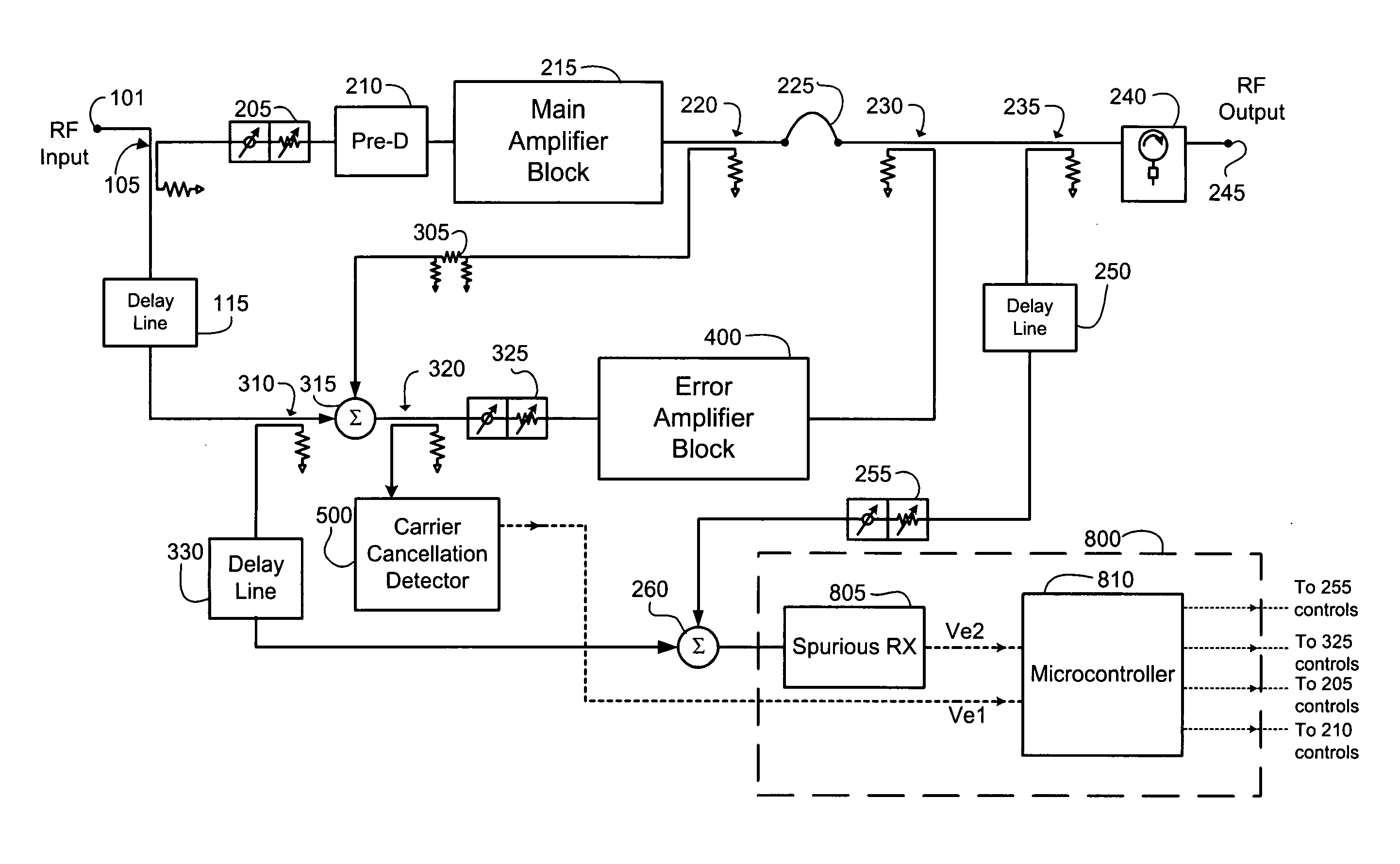
[0032] The present invention is generally directed to feed forward power amplifiers used for amplification of RF signals and a preferred embodiment is shown in FIG. 7. Various aspects of the invention may be utilized in other amplifier architectures and implementations, however, and the preferred embodiment described below is purely illustrative in nature.

[0033] First, referring to FIG. 7 the general architecture and principles of operation of the present invention will be described. In the illustrated preferred embodiment a feed forward power amplifier is disclosed which utilizes three signal cancellation loops. Loop 1 comprises main amplifier block (or module) 215 and associated couplers and interconnections and is used to derive a carrier cancelled signal at the first summing junction or (carrier cancellation combiner) 315. Loop 2 comprises error amplifier block (or module) 400 and associated couplers and interconnections. Loop 2 is used to amplify the carrier cancelled signal d...


PUM


Abstract

A delay mismatched feed forward power amplifier is disclosed. Loop 1 includes a main amplifier and is used to derive a carrier cancelled sample of the main amplifier output. Loop 2 includes an error amplifier used to amplify the carrier cancelled signal derived from Loop 1 operation in order to cancel distortion products generated due to the nonlinear nature of the main amplifier. Loop 2 also utilizes a very short Loop 2 delay line. A significant efficiency gain is provided due to reduced output power losses associated with the Loop 2 delay line. Lower output losses also results in lower distortion levels produced by the main amplifier. This, in turn, reduces the size and performance requirements placed on the error amplifier. A smaller and more efficient error amplifier is employed resulting in further amplifier system efficiency improvement. The delay mismatch is compensated by a third control loop, a special adaptive control algorithm or a combination thereof.

Description

RELATED APPLICATION INFORMATION [0001] The present application is a continuation in part of application Ser. No. 10 / 775,799 filed on Feb. 10, 2004, which claims priority under 35 USC section 119(e) to provisional application Ser. No. 60 / 447,772 filed on Feb. 14, 2003. The present application is also a continuation in part of application Ser. No. 11 / 288,580 filed on Nov. 29, 2005, which is a divisional of Ser. No. 10 / 733,498 filed on Dec. 11, 2003, U.S. Pat. No. 7,002,407 issued on Feb. 21, 2006 which claims priority under 35 USC section 119(e) to provisional application Ser. No. 60 / 501,911 filed on Sep. 10, 2003 and provisional application Ser. No. 60 / 434,825 filed on Dec. 18, 2002. The disclosures of all the above noted applications and patent are incorporated herein by reference in their entirety.BACKGROUND OF THE INVENTION [0002] 1. Field of the Invention [0003] The present invention relates to RF power amplifiers and methods of amplifying an RF signal. More particularly, the pre...

Claims


Application Information

Patent Timeline
Patent Type & Authority Applications(United States)
IPC IPC(8): H03F1/26
CPCH03F1/32H03F1/3223H03F1/3229H03F2201/3212H03F2200/204H03F2200/321H03F1/3235
Inventor ARBAB, EZMARAIGURVICH, MARKHUNTON, MATTHEW J.RABINOVICH, ALEXANDERVASSILAKIS, BILL
Owner INTEL CORP
Why Eureka
Try Eureka