Metal tube assembly and radio frequency identification (RFID) tag

a technology of radio frequency identification and metal tubes, which is applied in the field of assembly of metal tubes and radio frequency identification (rfid) labels, can solve the problems of inability to print durable prints on metal tubes, inability to meet the needs of users, so as to reduce the flow resistance, avoid electromagnetic shielding effects of readers, and reduce the effect of separation

Inactive Publication Date: 2007-01-25
SIDERCA SAIC
View PDF15 Cites 13 Cited by
  • Summary
  • Abstract
  • Description
  • Claims
  • Application Information

AI Technical Summary

Benefits of technology

[0019] Separation between metal surface and label should also be optimized in order to avoid electromagnetic shielding effects from reader. The object is to obtain the smaller possible separation so as to prevent normal handling of tubes from being affected in the manufacturing plant, during transit or end use thereof, while still allowing labels reading. Another object is to reduce the flow resistance produced by the identification element around the tube. In other words, fluids flowing conditions around the tube should be modified as little as possible.
[0020] Label may be attached to tube by different elements. Said elements purpose is also to protect label from friction, impact, release forces, environmental conditions or the like. In other words, different attachment means will protect labels from the different effects generated by tubes manufacturing, storage, handling, transportation and commissioning processes.

Problems solved by technology

However, codes printed on a metal surface become eventually useless due to the deterioration of identification marks, which become dirty or are deleted until they disappear, rendering viewing thereof difficult.
At present there do not exist durable prints on metal tubes, due to the harsh conditions of tubes manufacturing processes, transport requirements and extended exposures to humidity and other environmental conditions.
It is known that these kind of structures are subject to adverse conditions during handling, transport and use, and thence it is required a high performance identification system, particularly in the case of hostile well operation conditions (high temperature, exposure to solvents, hydrocarbons, hot aqueous solutions, etc.).
As previously mentioned, durability of the above identification and tracking devices is very limited, due to the environmental hostility once tubes are delivered from the manufacturing plant, because of storage, handling, transport and use in wells; reading of said identification elements being further susceptible of being affected by the electromagnetic shielding generated by metal tubes on which such elements are fixed.
On the other hand, in those cases in which an electromagnetic screen or shield is used in order to attenuate said shielding effect, the identification element becomes voluminous, it being then subject to transport and handling risks as already mentioned.
Said labels may be read through a wide variety of substances such as snow, fog, ice, paint or other similarly discouraging environmental conditions which render bar codes and other optical reading technologies useless.

Method used


Image

  • Metal tube assembly and radio frequency identification (RFID) tag
  • Metal tube assembly and radio frequency identification (RFID) tag
  • Metal tube assembly and radio frequency identification (RFID) tag

Examples


Embodiment Construction

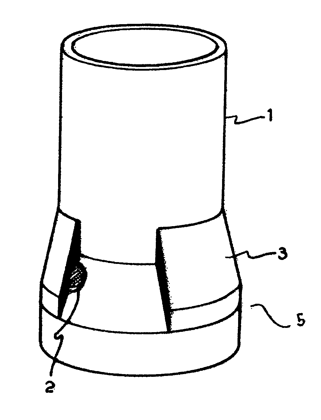
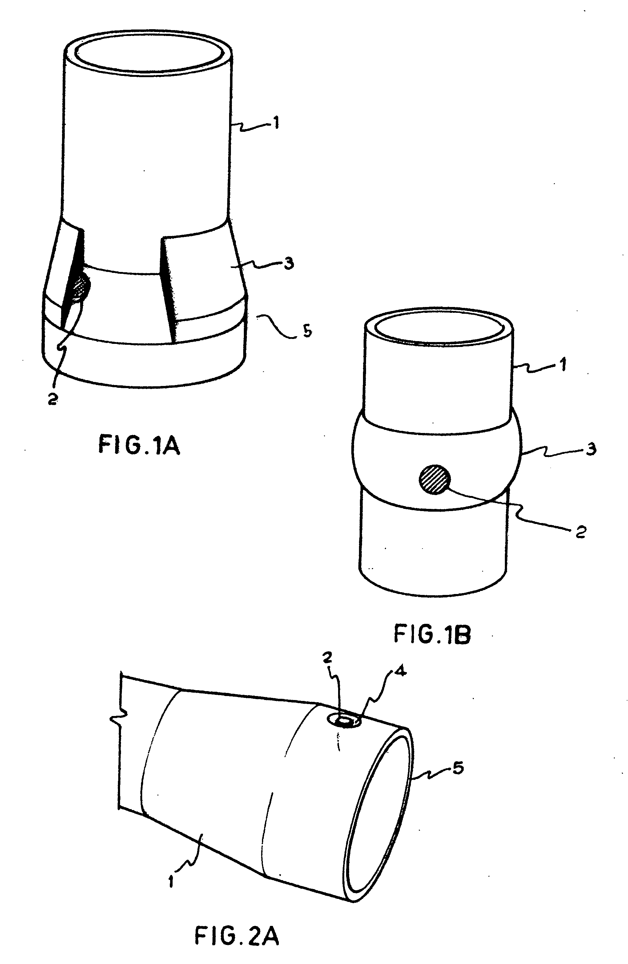
[0036]FIG. 1A illustrates a portion of a metal tube 1 which includes an radio-frequency identification (RFID) label 2 on the conical upset region 5 of tube 1. Said label 2 is surrounded by an attachment means such as for example a molded plastic ring 3 which may be injection-molded (when made of thermo-plastic material), casted or made by reaction injection (when made of thermo-rigid material), in such a way that it firmly fixes said label 2 on said metal tube 1. A thermo-shrinkable blanket (not illustrated) could be also used instead of said molded plastic ring 3.

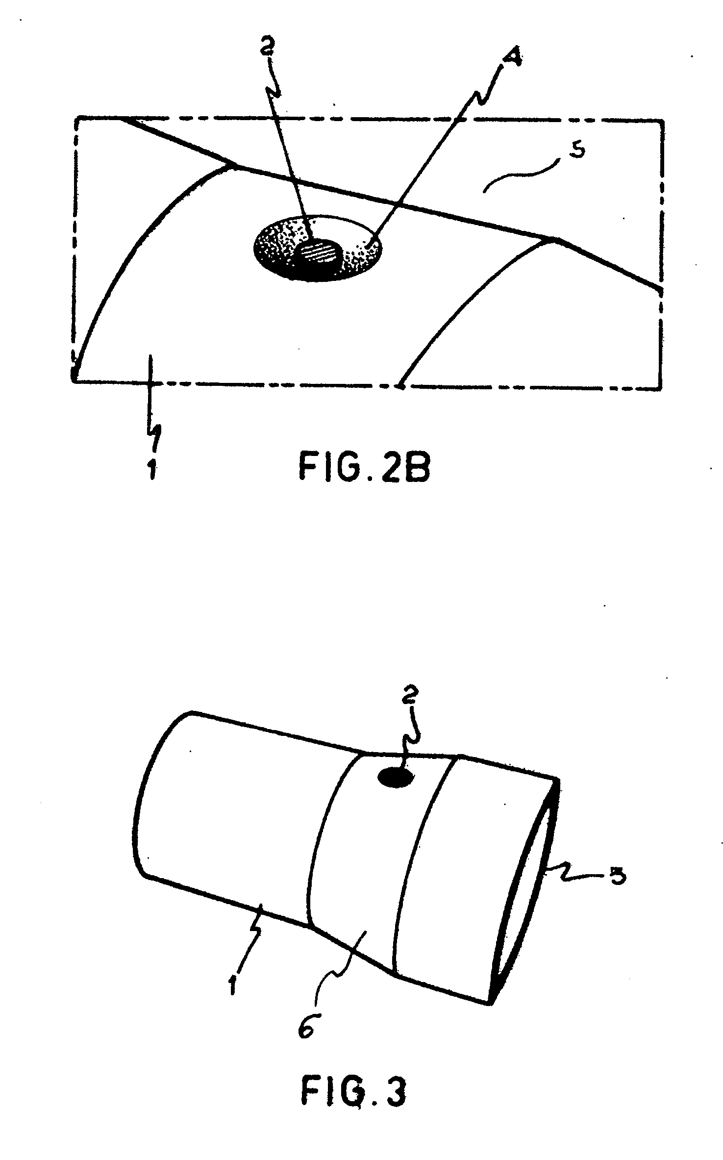
[0037]FIG. 1B illustrates the same molded plastic ring 3 which includes a label 2, but placed on the cylindrical region of tube 1.

[0038] Labels 2 may form a single structure with the different attachment means. In such case same may be included when molding plastic ring 3.

[0039] Molded plastic ring 3 may be thermo-plastic or thermo-rigid, with good mechanical properties and an excellent chemical resistance against the e...


PUM


Abstract

An assembly of metal tube and radio-frequency identification (RFID) labels is provided. RFID labels are attached to the external surface of a tube and are placed at a distance less than 1 mm from the external surface.

Description

FIELD OF THE INVENTION [0001] This patent refers to an assembly of metal tube and radio-frequency identification (RFID) labels applied on said tube. BACKGROUND OF THE INVENTION [0002] There currently exists an increasing interest in the tracking of serial manufactured metal tubes, not only as regards the internal tracking within the premises but also after such tubes are delivered. There exists a large variety of identification and tracking methods which involve printing of symbols (numbers, bar codes, brands, etc.,) by means of electrolytic attack, machining, laser, identification bands, releasable labels, electronic cards or modules, which may be implanted inside or outside the metal tube. [0003] However, codes printed on a metal surface become eventually useless due to the deterioration of identification marks, which become dirty or are deleted until they disappear, rendering viewing thereof difficult. At present there do not exist durable prints on metal tubes, due to the harsh ...

Claims


Application Information

Patent Timeline
Patent Type & Authority Applications(United States)
IPC IPC(8): G08B13/14
CPCB65C3/02G06K19/07771B65C2009/0003
Inventor MORBITZER, NELSON MARIO PACHAOERNST, HUGO ALEJANDROHERITIER, LUIS ROBERTO
Owner SIDERCA SAIC
Why Eureka
Try Eureka