Apparatus and method for facilitating cooling of an electronics rack by mixing cooler air flow with re-circulating air flow in a re-circulation region

a technology of electronics racks and apparatuses, applied in the direction of electrical apparatus casings/cabinets/drawers, cooling/ventilation/heating modifications, instruments, etc., can solve the problems of recirculation problems, difficulty in cooling, and difficulty in adjusting the approach, so as to facilitate mixing, facilitate cooling of electronics racks, and facilitate the effect of lowering the air inlet temperatur

Active Publication Date: 2007-01-25
IBM CORP
View PDF15 Cites 54 Cited by
  • Summary
  • Abstract
  • Description
  • Claims
  • Application Information

AI Technical Summary

Benefits of technology

[0008] The shortcomings of the prior art are overcome and additional advantages are provided through an apparatus for facilitating cooling of an electronics rack. The apparatus includes an outlet door configured to mount to and at least partially cover an air outlet side of an electronics rack. The outlet door includes a first section and a second section. The first and second sections of the door are configured to re-direct at least a portion of exiting inlet-to-outlet air flow of the electronics rack, and to exhaust the re-directed air fl

Problems solved by technology

This trend poses a cooling challenge at both the module and system level.
However, this approach is becoming problematic at the rack level in the context of a computer installation (e.g., data center).
In such installations, not only will the room air conditioning be challenged, but the situation may also result in re-circulation problems with some fraction of the “hot” air exiting one

Method used


Image

  • Apparatus and method for facilitating cooling of an electronics rack by mixing cooler air flow with re-circulating air flow in a re-circulation region
  • Apparatus and method for facilitating cooling of an electronics rack by mixing cooler air flow with re-circulating air flow in a re-circulation region
  • Apparatus and method for facilitating cooling of an electronics rack by mixing cooler air flow with re-circulating air flow in a re-circulation region

Examples


Embodiment Construction

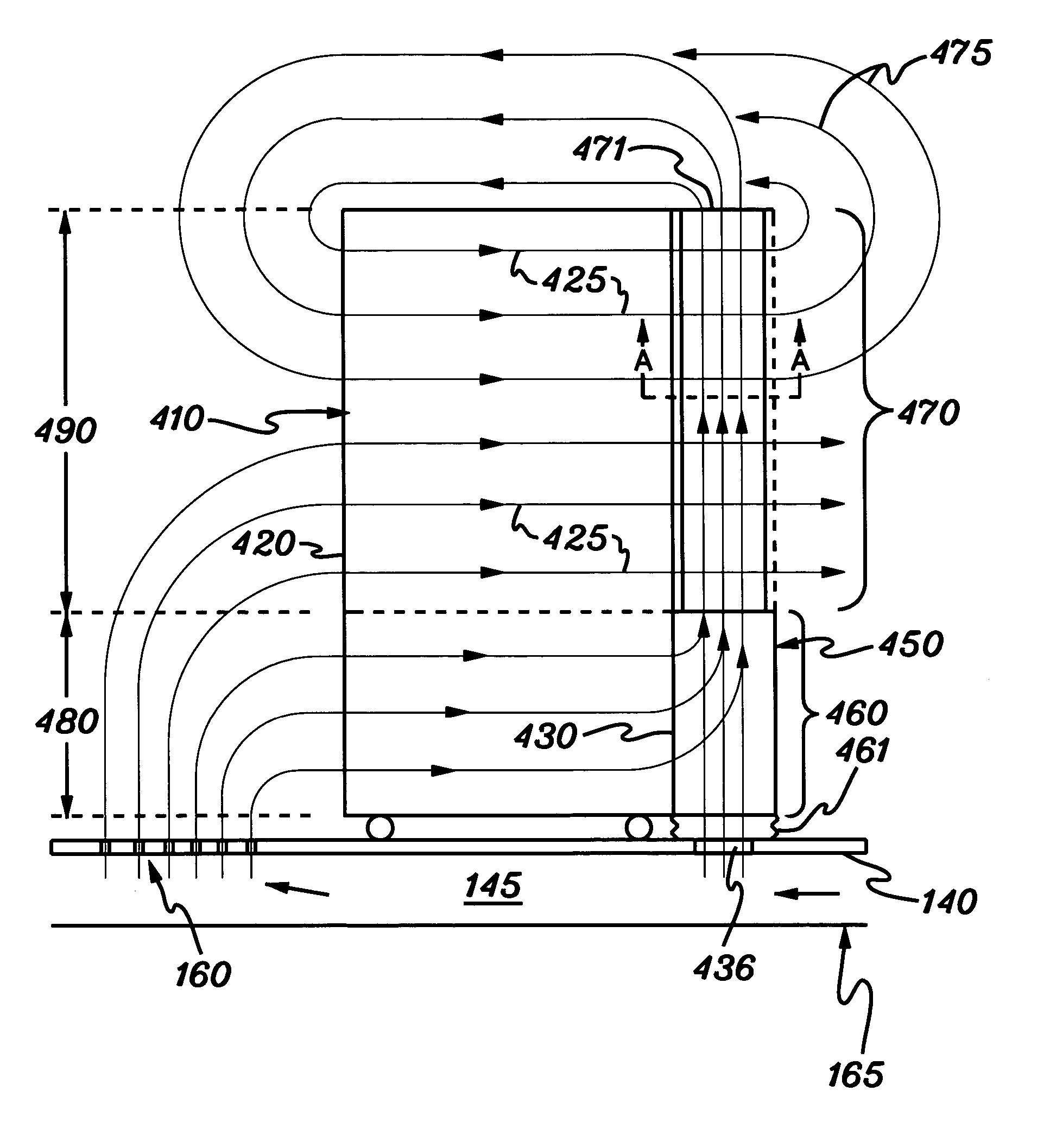
[0025] As used herein, the terms “electronics rack”, “rack-mounted electronic equipment”, and “rack unit” are used interchangeably, and include any housing, frame, rack, compartment, blade server system, etc., having one or more heat generating components of a computer system or electronics system, and may be, for example, a stand alone computer processor having high, mid or low end processing capability. In one embodiment, an electronics rack may comprise multiple electronics drawers each having one or more heat generating components disposed therein requiring cooling. Further, as used herein, “heat exchanger” means any heat exchange mechanism through which coolant can circulate; and includes, one or more discrete heat exchange devices coupled either in series or in parallel.

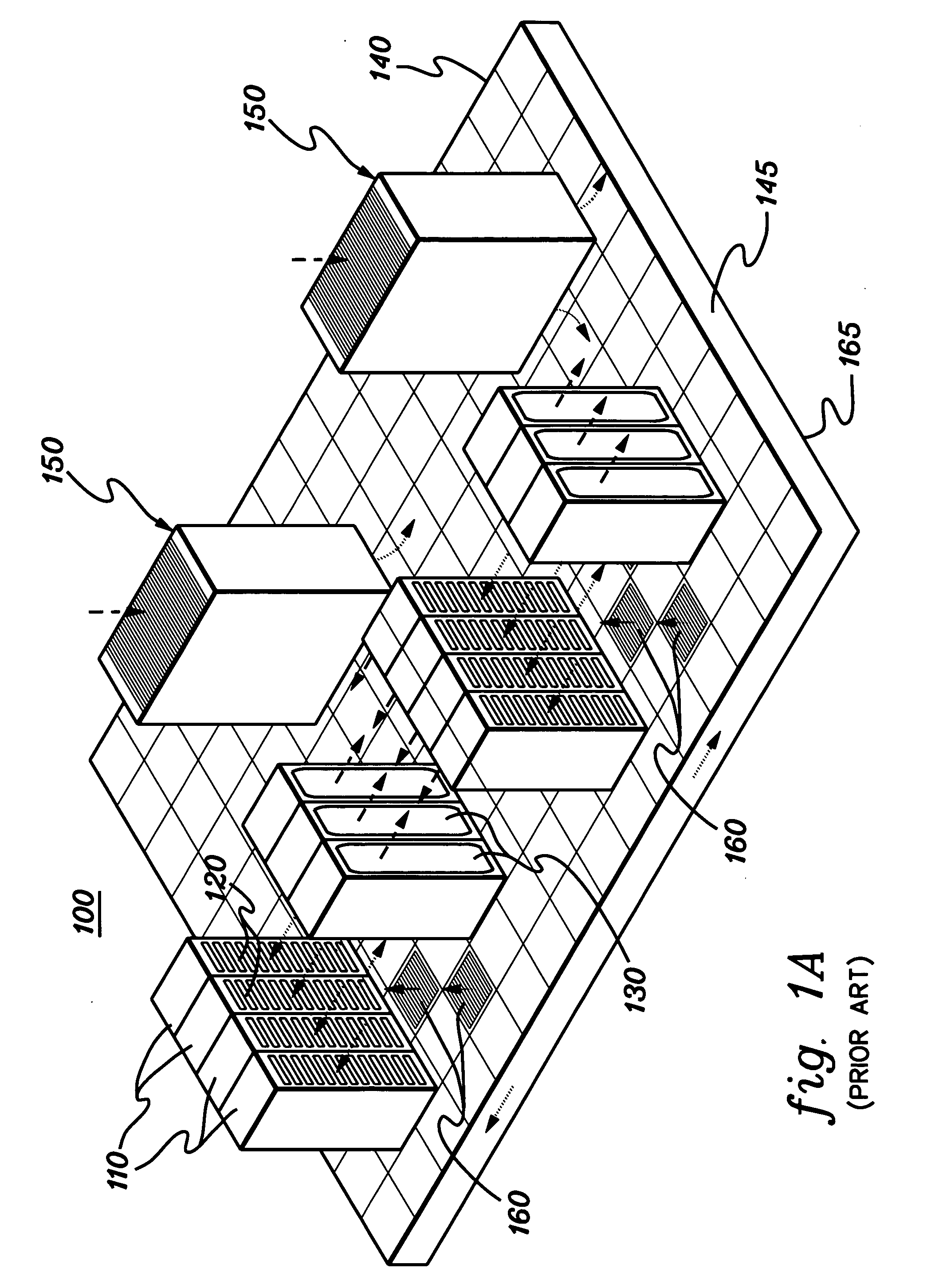
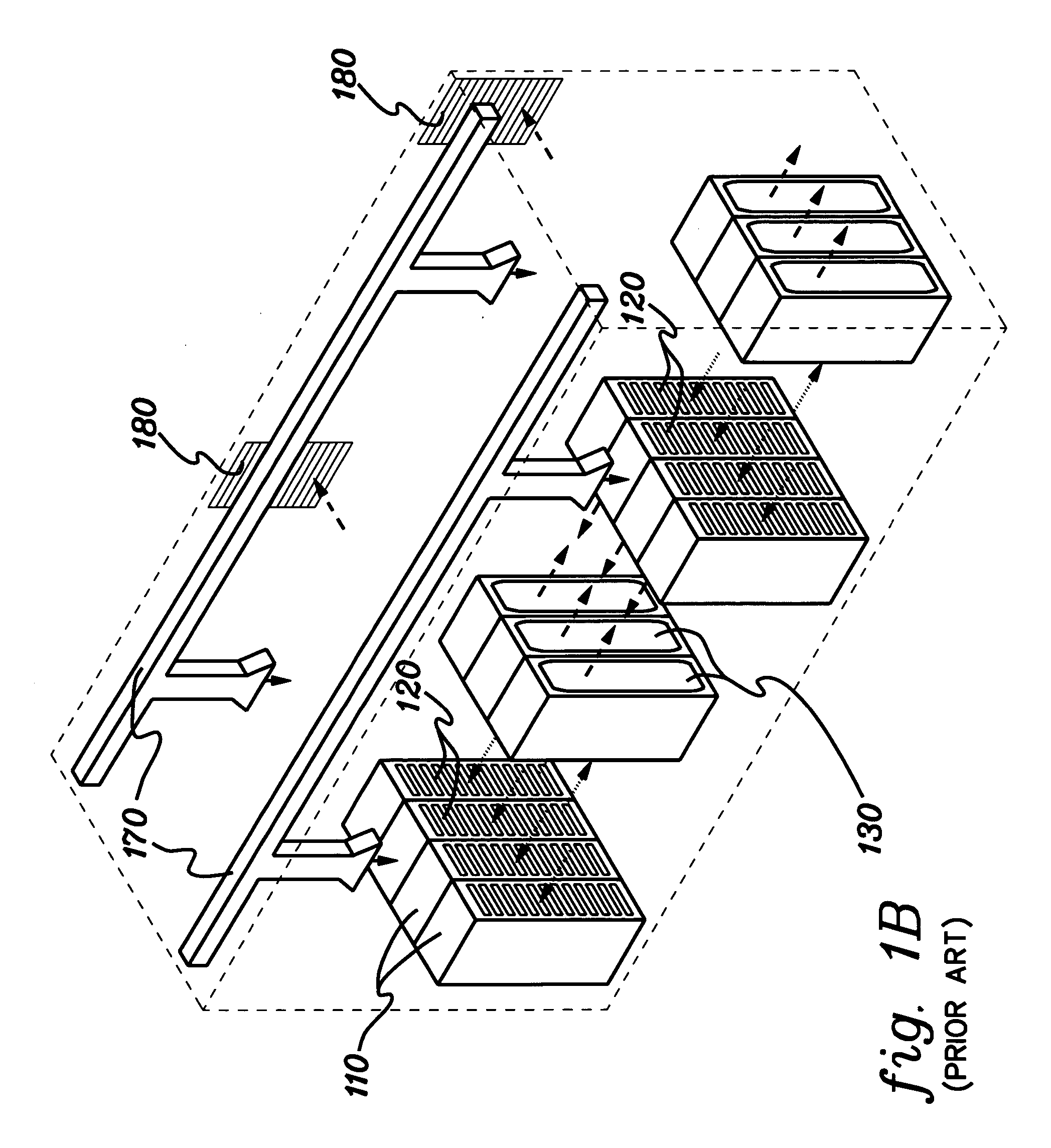
[0026] Reference is now made to the drawings, which are not drawn to scale for reasons of understanding, wherein the same reference numbers used throughout different figures designate the same or similar compo...


PUM


Abstract

Apparatus and method are provided for facilitating cooling of an electronics rack employing an air delivery structure coupled to the electronics rack. The air delivery structure delivers air flow at a location external to the electronics rack and in a direction to facilitate mixing thereof with re-circulating exhausted inlet-to-outlet air flow from the air outlet side of the electronics rack to the air inlet side thereof. The delivered air flow is cooler than the re-circulating exhausted inlet-to-outlet air flow and when mixed with the re-circulating air flow facilitates lowering air inlet temperature at a portion of the air inlet side of the electronics rack, thereby enhancing cooling of the electronics rack.

Description

CROSS-REFERENCE TO RELATED APPLICATION [0001] This application contains subject matter which is related to the subject matter of the following U.S. patent application, which is assigned to the same assignee as this application and which is hereby incorporated herein by reference in its entirety: [0002]“Apparatus and Method for Facilitating Cooling of an Electronics Rack Employing a Closed Loop Heat Exchange System”, by Campbell et al., Ser. No. 11 / 124,525, filed May 6, 2005. TECHNICAL FIELD [0003] The present invention relates in general to apparatuses and methods for facilitating cooling of rack-mounted assemblages of individual electronics units, such as rack-mounted computer server units. BACKGROUND OF THE INVENTION [0004] The power dissipation of integrated circuit chips, and the modules containing the chips, continues to increase in order to achieve increases in processor performance. This trend poses a cooling challenge at both the module and system level. Increased air flow r...

Claims


Application Information

Patent Timeline
IPC IPC(8): H05K7/20
CPCF24F13/04H05K7/20745H05K7/20736
Inventor CAMPBELL, LEVI A.CHU, RICHARD C.ELLSWORTH,, MICHAEL J. JR.IYENGAR, MADHUSUDAN K.SCHMIDT, ROGER R.SIMONS, ROBERT E.
Owner IBM CORP
Why Eureka
Try Eureka