Backlight unit and liquid crystal display comprising the same

a backlight unit and liquid crystal display technology, applied in the direction of planar/plate-like light guides, lighting and heating apparatus, instruments, etc., can solve the problems of low optical efficiency of the edge-type backlight unit, inability to manufacture a single mold, and uneven brightness, so as to achieve enhanced color uniformity and optical efficiency

Inactive Publication Date: 2007-01-25
SAMSUNG ELECTRONICS CO LTD
View PDF22 Cites 60 Cited by
  • Summary
  • Abstract
  • Description
  • Claims
  • Application Information

AI Technical Summary

Benefits of technology

[0009] The present general inventive concept provides a backlight unit and an L...

Problems solved by technology

However, the emitted light is attenuated while passing the light guide plate, so that optical efficiency of the edge type backlight unit is relativel...

Method used


Image

  • Backlight unit and liquid crystal display comprising the same
  • Backlight unit and liquid crystal display comprising the same
  • Backlight unit and liquid crystal display comprising the same

Examples


Embodiment Construction

[0040] Reference will now be made in detail to the embodiments of the present general inventive concept, examples of which are illustrated in the accompanying drawings, wherein like reference numerals refer to like elements throughout. The embodiments are described below in order to explain the present general inventive concept by referring to the figures.

[0041] Hereinafter, a light emitting diode (LED) will be described as an example of a point light source. However, the present general inventive concept is not limited to the point light source being an LED.

[0042] An LCD according to an embodiment of the present general inventive concept will be described with reference to FIGS. 1 through 3.

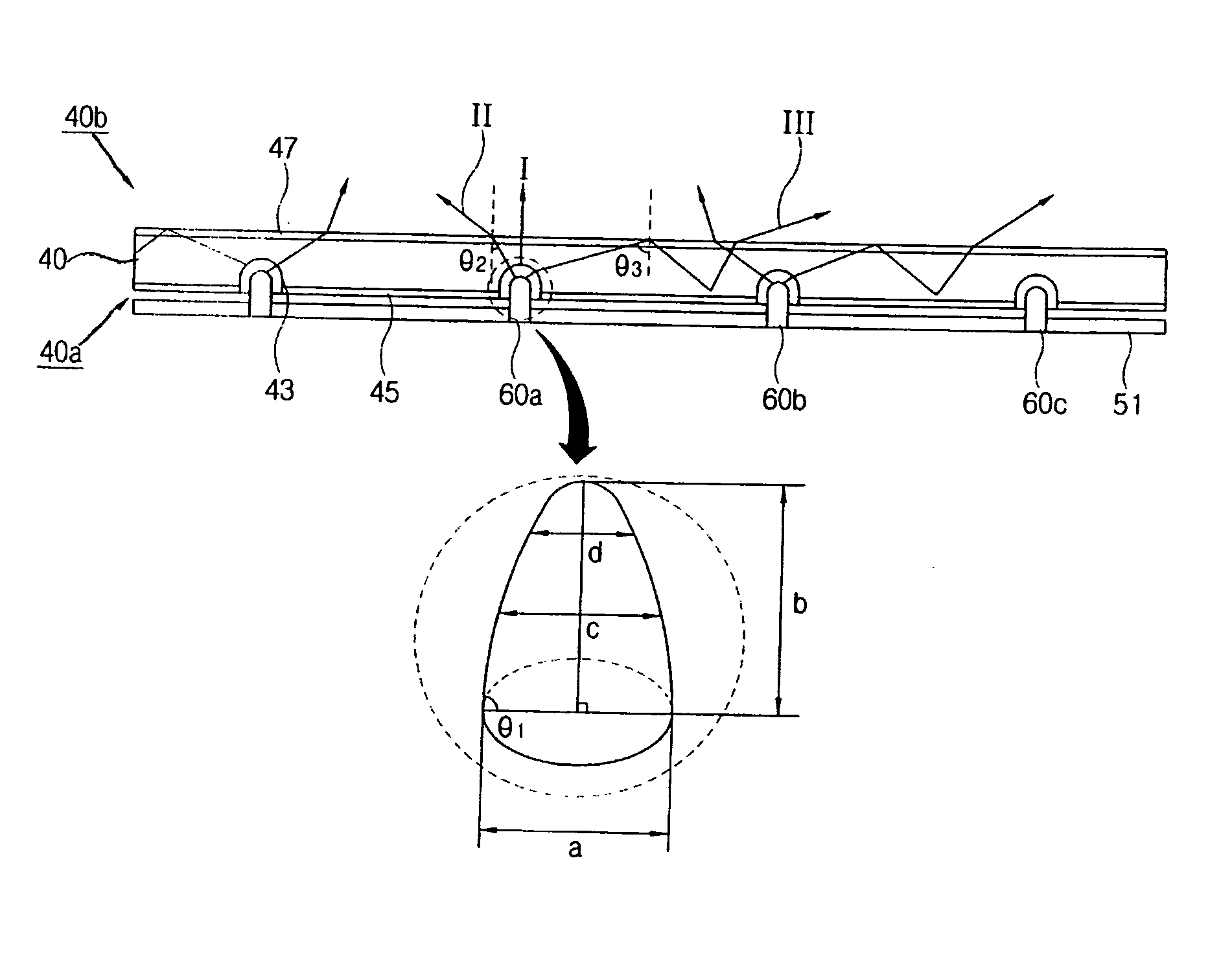
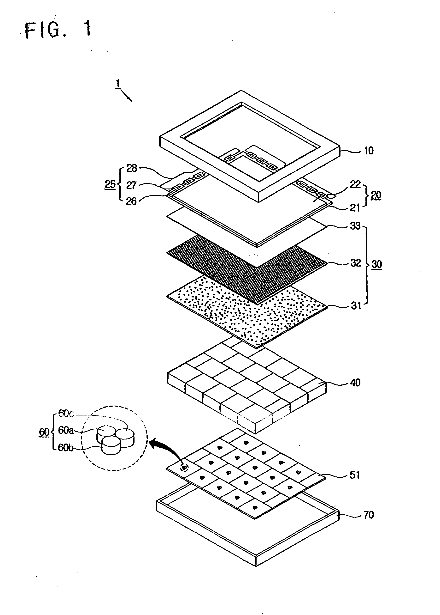
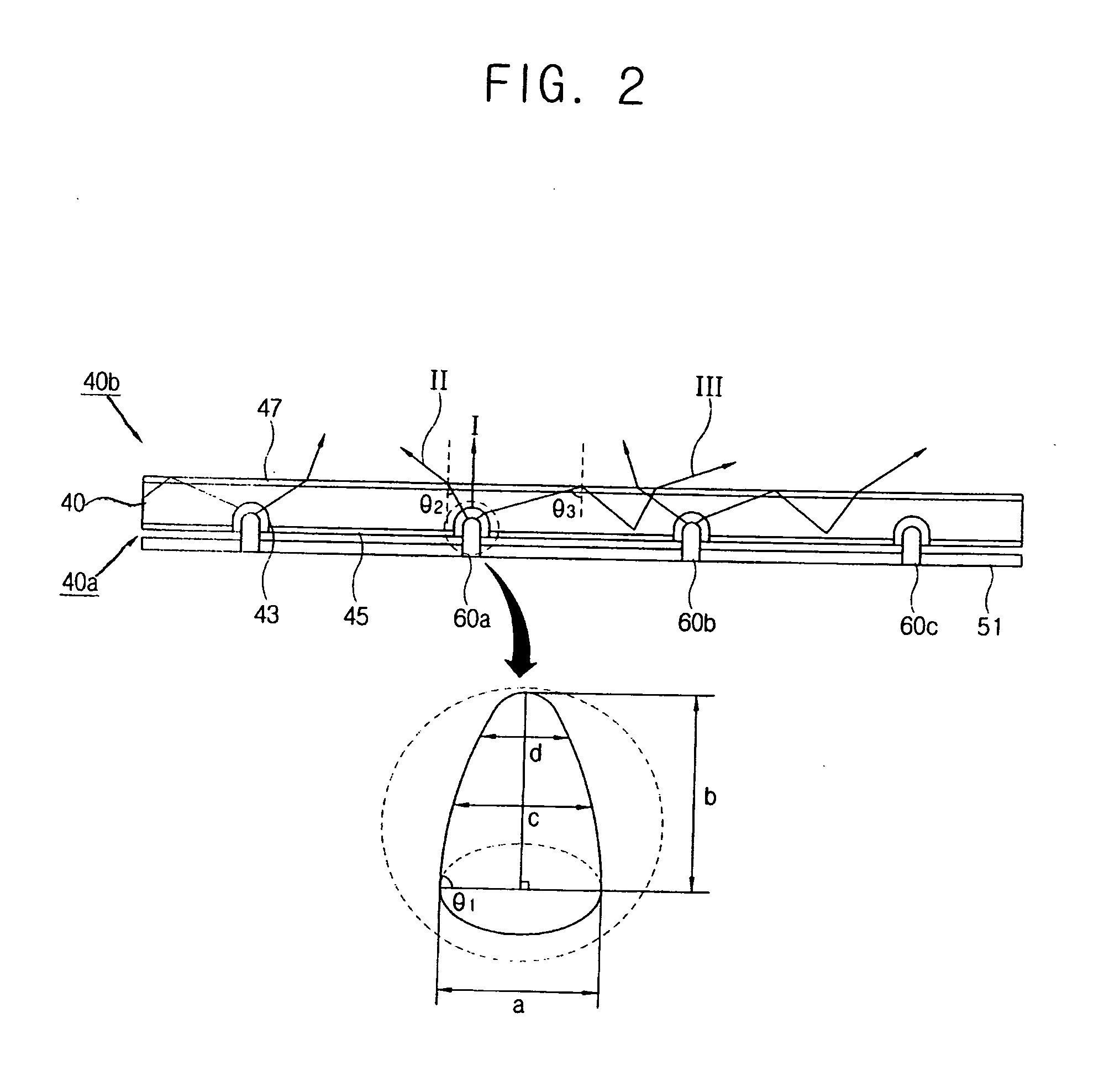
[0043]FIG. 1 is an exploded perspective view illustrating an LCD according to an embodiment of the present general inventive concept, FIG. 2 is a sectional view illustrating the LCD in FIG. 1, and FIG. 3 is a graph illustrating a non-uniformity of color in the LCD of FIG. 1.

[0044] The LCD 1 ...


PUM


Abstract

A backlight unit includes a point light source circuit board, a plurality of point light sources mounted onto the point light source circuit board, and an optical plate having a first surface that faces toward the point light source and is formed with an accommodating part to accommodate the point light source.

Description

CROSS-REFERENCE TO RELATED APPLICATIONS [0001] This application claims priority under 35 U.S.C. §119(a) from Korean Patent Application No. 2005-0066914, filed on Jul. 22, 2005, in the Korean Intellectual Property Office, the disclosure of which is incorporated herein by reference. BACKGROUND OF THE INVENTION [0002] 1. Field of the Invention [0003] The present general inventive concept relates to a backlight unit and a liquid crystal display (LCD) including the same, and more particularly, to a backlight unit and an LCD including the same, in which the backlight unit includes an optical plate to enhance a color mixture of point light sources. [0004] 2. Description of the Related Art [0005] Recently, various flat panel displays such as a liquid crystal display (LCD), a plasma display panel (PDP), an organic light emitting diode (OLED), etc. have been developed as an alternative to a cathode ray tube (CRT). [0006] Among them, the LCD includes an LCD panel that has a thin film transisto...

Claims


Application Information

Patent Timeline
IPC IPC(8): G01D11/28
CPCG02B6/0018G02F1/133603G02B6/0068G02B6/0021G02F1/1335
Inventor PARK, HYE-EUNJANG, DONG-SEOBYOUN, SEONG-HOKIM, CHANG-JULEE, SEUNG-JAE
Owner SAMSUNG ELECTRONICS CO LTD
Why Eureka
Try Eureka