Direct casting utilizing stack filtration

a technology of filtration system and casting casting, applied in the field of casting, can solve the problems of casting to be reworked or scrapped, the impurity content of direct casting of super alloys and other metals for precision casting components is high, and the impurity content of direct casting is high

Inactive Publication Date: 2007-02-01
AJAX MAGNETHERMIC CORP
View PDF8 Cites 17 Cited by
  • Summary
  • Abstract
  • Description
  • Claims
  • Application Information

AI Technical Summary

Benefits of technology

[0011] The present invention provides a method comprising the steps of pre-heating at least one filter to a filter temperature which will prevent breakage of the filter due to thermal shock from contact with molten material; and passing molten material through the at least one filter.

Problems solved by technology

In the melting, casting and / or other processing of metals or other materials, there is often a substantial amount of impurities within the metal or other materials to be melted.
Separating these impurities from the desired material which is ultimately to be used in a finished product presents a host of problems.
It has long been understood that the direct casting of super alloys and other metals for precision casting components has suffered from impurities entrapped in the master melt alloy.
The impurities become entrapped within the casting or on the surface thereof and often cause the casting to be reworked or scrapped.
Filtering is often used to help remove these impurities; however, conventional filtration techniques often cause more inclusions than they prevent.
In this system and method, the filter is maintained at or close to the shell temperature, which is significantly lower than the alloy pour temperature and thus can negatively effect the pour temperature and if the alloy freezes, the filters can become clogged.
Because of the difference in temperatures, thermal shock can occur and cause fragments of the filter to break off and enter the shell of the mold.
Such problems greatly reduce the overall effectiveness of pour cup filtering.
The filters at these shell temperatures can negatively effect the pour temperature and clog the filters if the alloy freezes.
In addition, the material used to affix the filter in place may be a contaminant as well.
This puts considerable stress on the ceramic filters leading to loose fragments that can enter the mold.
After solidification, metal is imbedded in the filter and cannot be readily reverted.
Thus, bottom feeding is effective, but comes at a significant alloy cost.
In addition, the bottom feed filter system may prevent tight baffling of the components and affect grain quality.
Also, since the temperature is lower than the solidification point of the alloy, any interruption in pouring may cause the system to freeze prematurely, resulting in the need to replace the tundish or eliminate its use for the remainder of the pour.
In addition, because the tundish assembly is preheated offline and then moved into the pouring position without additional heating, this configuration and method would not allow for the use of fine filters.

Method used


Image

  • Direct casting utilizing stack filtration
  • Direct casting utilizing stack filtration
  • Direct casting utilizing stack filtration

Examples


Embodiment Construction

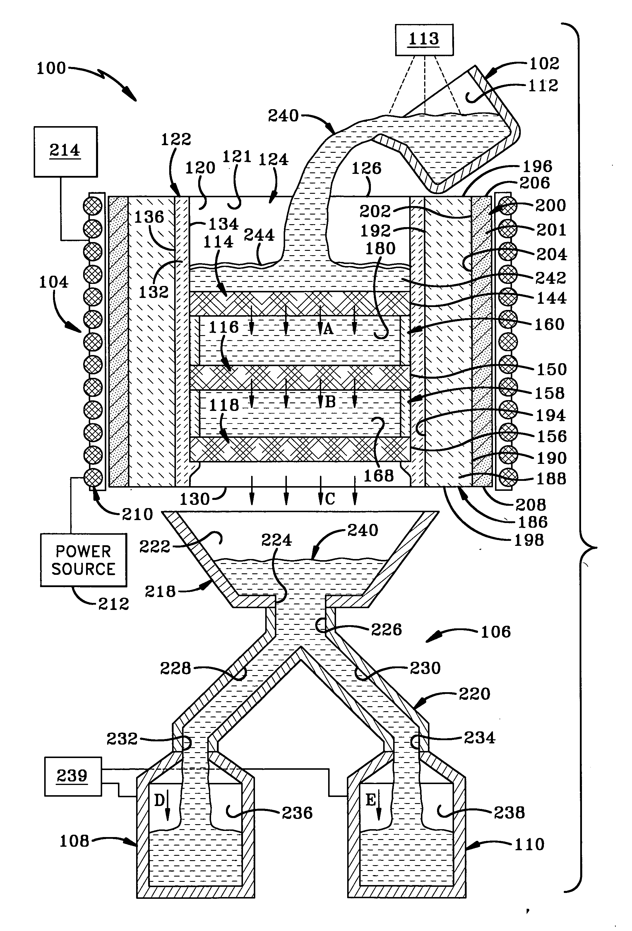
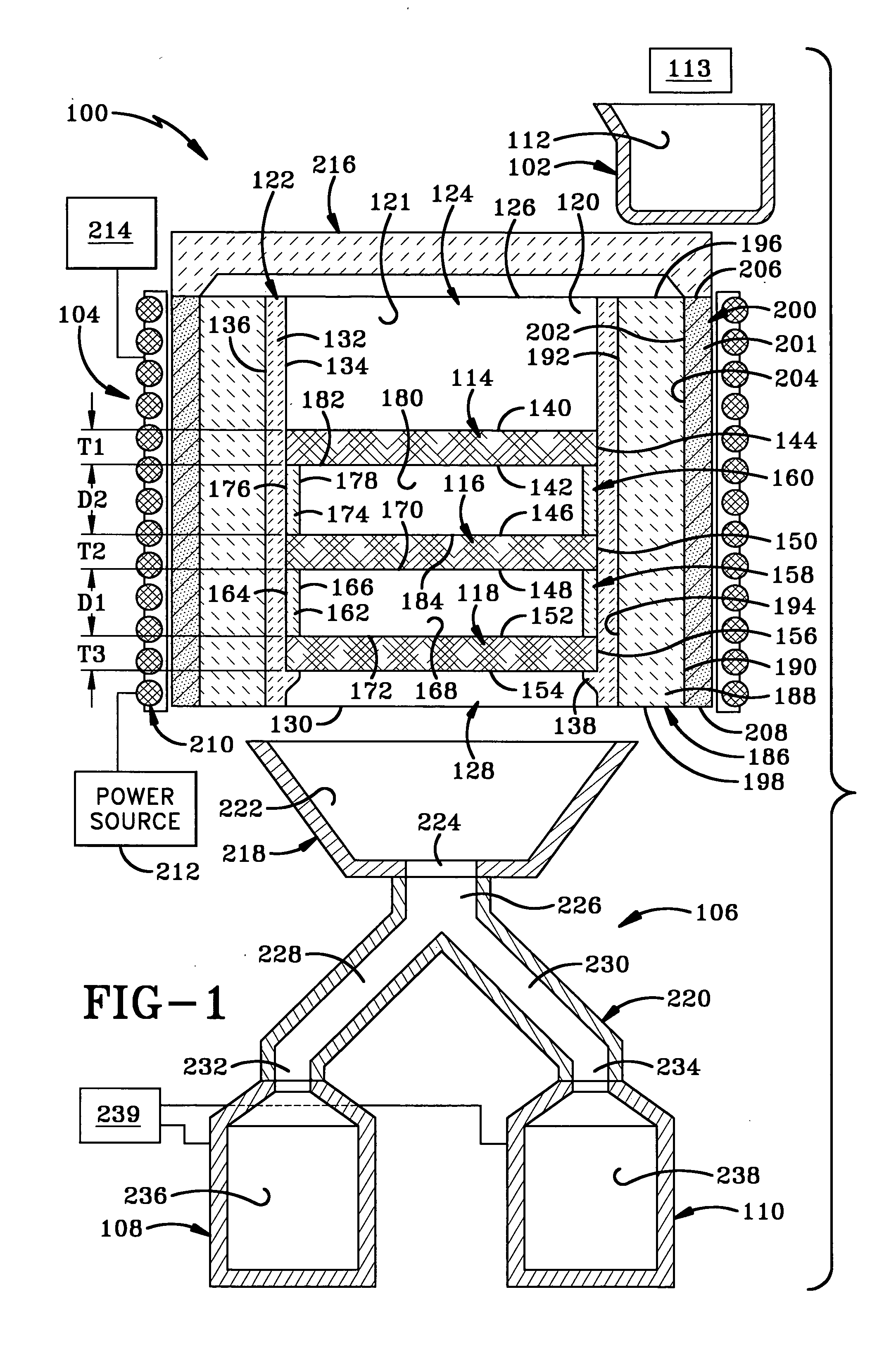
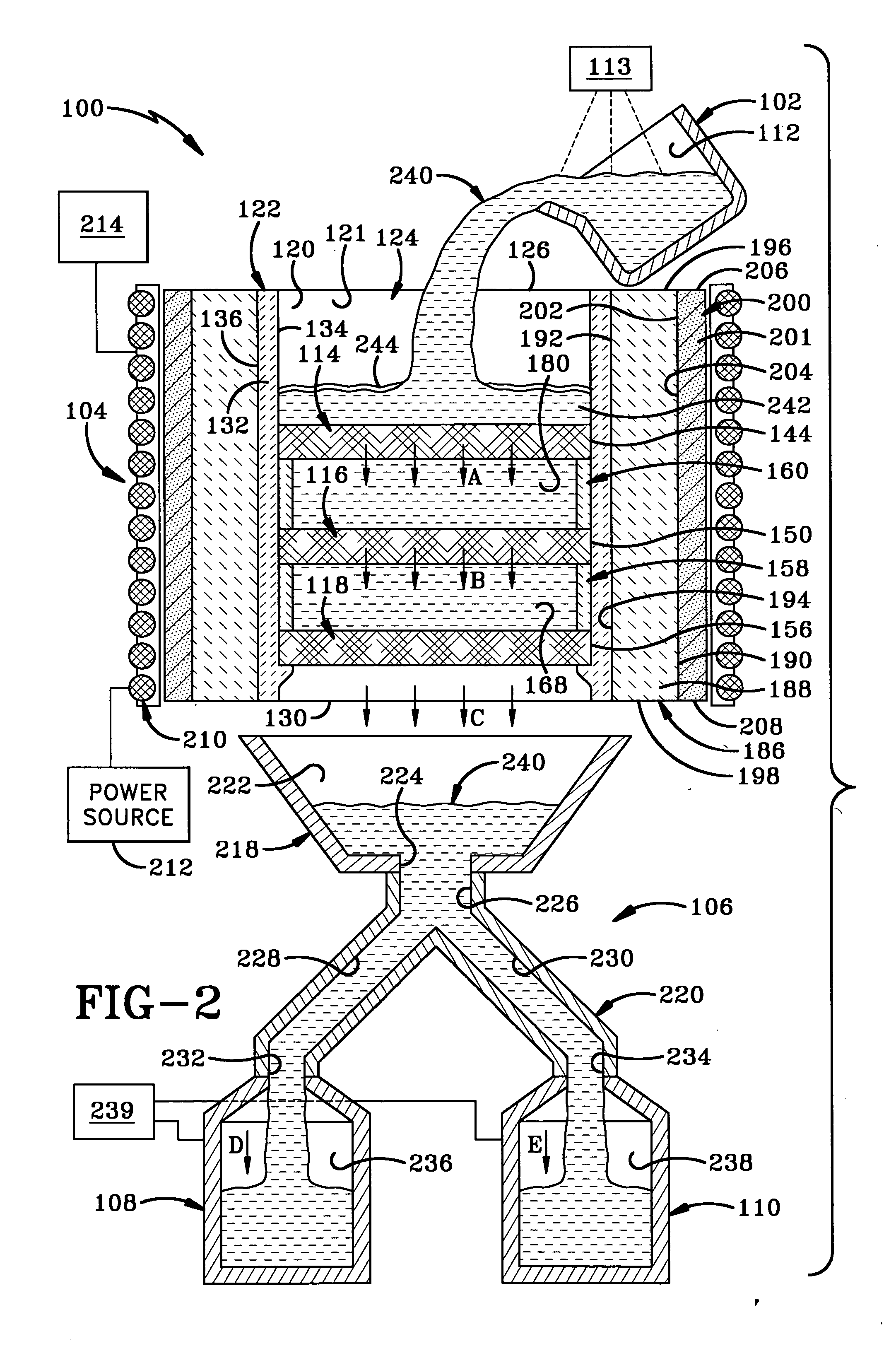
[0019] A first embodiment of the casting system of the present invention is indicated generally at 100 in FIGS. 1-2; a second embodiment is indicated generally at 300 in FIG. 3; and a third embodiment is indicated generally at 400 in FIG. 4.

[0020] Casting system 100 includes a pouring vessel 102 which is often a melting crucible, a filtration system or assembly 104 disposed below vessel 102, a transferring system or shell or assembly 106 disposed below assembly 104 and first and second containing vessels in the form of molds 108 and 110 disposed below transferring assembly 106. Typically, assembly 106 and molds 108 and 110 are a single assembly.

[0021] Pouring vessel 102 defines a cavity 112 for containing molten material. Vessel 102 is typically either a main melt furnace in which material is melted or a refining hearth which receives molten material from the main melt furnace. Pouring vessel 102 is disposed above filtration assembly 104 for pouring molten material into assembly 1...


PUM

PropertyMeasurementUnit
pouring temperatureaaaaaaaaaa

Abstract

A casting system includes a filtration assembly including a filter vessel housing spaced filters pre-heated to a temperature approximating a pouring temperature of molten material to be filtered to prevent breakage of the filter due to thermal shock from contact with the molten material. Preferably, an induction coil is used to inductively heat a susceptor adjacent the filter vessel or inductively heat filters which themselves serve as susceptors. Typically, the filter vessel is disposed below a pouring vessel and above a mold, pour cup and any sprue system used and is heated independently from the same. The filters are heated during pouring to facilitate flow of the molten material therethrough whereby very fine filters may be used. Spacing of the filters enhances flow control and allows a head of molten material to form whereby dross floats to the top of the head to prevent its entry into the mold.

Description

CROSS REFERENCE TO RELATED APPLICATIONS [0001] This application claims priority from U.S. Provisional Application Ser. No. 60 / 703,831 filed Jul. 29, 2005; the disclosure of which is incorporated herein by reference.BACKGROUND OF THE INVENTION [0002] 1. Technical Field [0003] The invention relates generally to the casting of molten metals or other molten / liquid materials. More particularly, the invention relates to a filtration system used for such melting and casting. Specifically, the invention relates to a filtration system wherein the filters are preheated to a temperature similar to a pouring temperature of the molten material to prevent breakage of the filters due to thermal shock and frozen metal clogging associated with temperature filtration. [0004] 2. Background Information [0005] In the melting, casting and / or other processing of metals or other materials, there is often a substantial amount of impurities within the metal or other materials to be melted. Separating these i...

Claims


Application Information

Patent Timeline
Patent Type & Authority Applications(United States)
IPC IPC(8): C22B9/02
CPCC22B9/023B22D43/004Y02P10/20
Inventor TODARO, THOMAS J.WARREN, DAVID O.LAZOR, DAVID A.SCHWENK, KARL J.KOHLER, MICHAEL W.
Owner AJAX MAGNETHERMIC CORP
Why Eureka
Try Eureka