Deflection magnetic field type vacuum arc vapor deposition device

a vacuum arc and vapor deposition technology, applied in vacuum evaporation coatings, electrolysis components, coatings, etc., can solve the problems of low uniformity in film thickness distribution, difficult to form the above film, and poor film quality and/or film thickness of the thin film. uniform, good quality, desired structure

Inactive Publication Date: 2007-02-01
NISSIN ELECTRIC CO LTD +1
View PDF5 Cites 7 Cited by
  • Summary
  • Abstract
  • Description
  • Claims
  • Application Information

AI Technical Summary

Benefits of technology

[0023] A state of arrangement of the deflection magnetic field forming member arranged at the filter duct can be adjusted by adjusting, e.g., the position of the member in the direction of extension of the duct, the angular position of the member with respect to the duct and / or a combination of such positions, and thereby it is possible to change characteristics (directions of lines of magnetic force and others) of magnetic field formed in the duct by the deflection magnetic field forming member. Thereby, it is possible to control the direction of flight of the ionized cathode material in the duct.
[0024] Accordingly, in connection with one, some or all of the plurality of filter ducts in the vacuum arc vapor deposition apparatus of the deflection field type and the common duct end type, the arrangement state of one, some or all of the deflection magnetic field forming members, which are provided for the filter duct(s), can be adjusted so that the flows of the ionized cathode materials produced from the respective vapor sources of the plurality of vapor deposition units can be joined together in the common duct end of the plurality of filter ducts, and thereby can be directed toward the deposition target on the holder. Thereby, even if the film to be formed is a compound film or the like, it is possible to form the film having good quality and desired structure on the deposition target with good productivity.

Problems solved by technology

This may lower the uniformity in film thickness distribution.
In the structure having the multiple kinds of vapor sources respectively arranged in different positions of one filter duct, however, it is practically difficult to form the above film on the deposition target arranged in a predetermined position because the ionized cathode material produced from each vapor source takes a path different from that of another ionized cathode material in the same filter duct.
In addition to the formation of the compound film, the formation of the thin film containing the base layer and the formation of the thin film containing an additional element may suffer form such a problem that the film quality and / or film thickness of the thin film may not be uniform because the several kinds of ionized cathode materials fly from different positions to the deposition target in the constant position.
Further, the filter ducks, which correspond in number to the vapor sources, are connected to different positions on the deposition container wall so that this structure impedes reduction in sizes of the vacuum arc vapor deposition apparatus.
However, if it is practically attempted to form a compound film or a composite film by the above apparatus, the deflection fields in the filter ducts 93 and 94 mutually affect so that flows 950 and 960 of the ionized cathode materials, which are produced from the vapor sources 95 and 96, respectively, may not join together to form a flow directed toward the deposition target s on the holder, but may be directed in different directions after or without crossing, respectively, Consequently, it may be difficult to form the desired compound film or the like on the deposition target s. Even in the case of forming, e.g., the film including the base layer or the film containing an additional element, it may be difficult to concentrate finally the respective ionized cathode material onto the deposition target s on the holder.

Method used


Image

  • Deflection magnetic field type vacuum arc vapor deposition device
  • Deflection magnetic field type vacuum arc vapor deposition device
  • Deflection magnetic field type vacuum arc vapor deposition device

Examples


Embodiment Construction

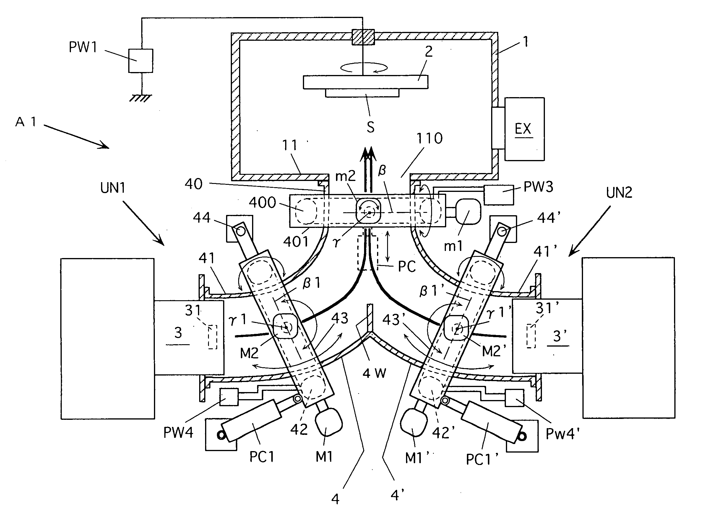
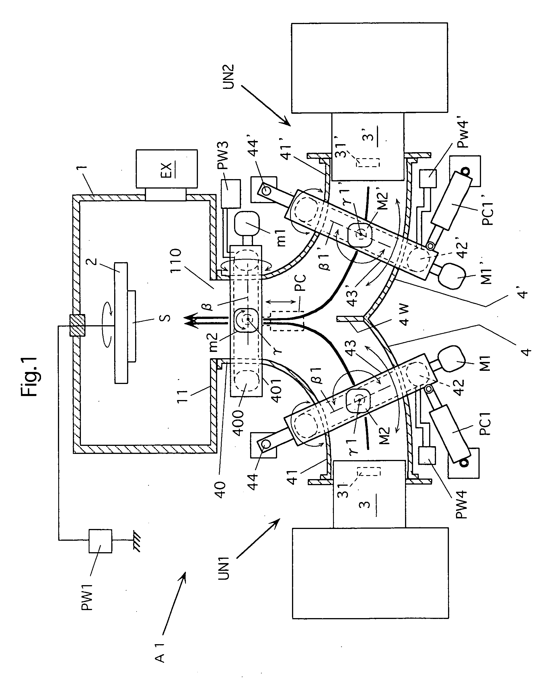
[0033] A vacuum arc vapor deposition apparatus of a deflection field type according to an embodiment of the invention includes a plurality of vapor deposition units each including a vapor source configured to vaporize and ionize a cathode material by a vacuum arc discharge between a cathode formed of the cathode material and an anode, and a curved filter duct provided with one or more deflection magnetic field forming members providing the ionized cathode material produced from the vapor source toward a holder holding a deposition target for forming a film containing a component element of the cathode material on the deposition target.

[0034] The curved filter ducts of the plurality of vapor deposition units have duct ends opposed to the holder and formed together to provide a common duct end. At least one vapor source is arranged on the other end of each of the filter ducts.

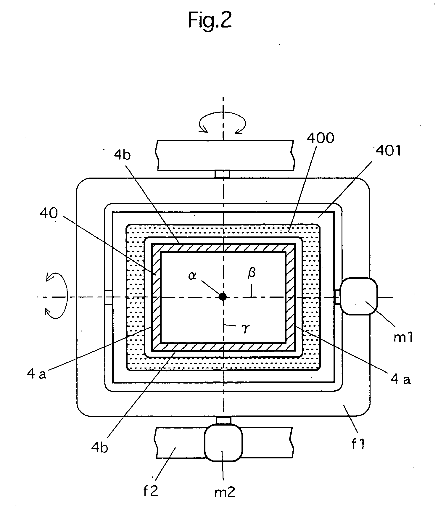
[0035] The above apparatus further includes a magnetic field forming member adjusting device adjusting a sta...


PUM

PropertyMeasurementUnit
magnetic fieldaaaaaaaaaa
deflection magnetic fieldaaaaaaaaaa
voltageaaaaaaaaaa

Abstract

A vacuum arc vapor deposition apparatus of a deflection field type includes a plurality of vapor deposition units (UN1, UN2) each including a vapor source (3, 3′) and a curved filter duct (4, 4′) provided with deflection field forming coils (400, 42 or 42′). The ducts (4, 4′) have duct ends opposed to the deposition target holder (2) and formed together to provide a common duct end (40). The vapor source (3, 3′) is arranged on the other end (41, 41′) of each duct. The coil (400) is arranged for the common duct end (40), and one magnetic field forming coil (42, 42′) is arranged for each of the ducts. An adjusting device (motors m1, m2 and drive device PC, motors M1, M2 and drive device PC1, motors M1′, M2′ and drive device PC1′) for adjusting a state of arrangement is arranged for each coil. This vacuum arc vapor deposition apparatus can form a thin film of good quality having a desired structure on the deposition target with good productivity.

Description

TECHNICAL FIELD [0001] The present invention relates to a vacuum arc vapor deposition apparatus, which can be used for depositing thin films on subjects or works such as automobile parts, machine parts, tools or dies for the purpose of, e.g., improving at least one of wear resistance, sliding property, corrosion resistance and others. BACKGROUND ART [0002] According to a vacuum arc vapor deposition apparatus, vacuum arc discharge is caused between an anode and a cathode to vaporize a cathode material by the arc discharge in a vacuum atmosphere, and plasma containing the ionized cathode material is produced to provide the ionized cathode material onto a deposition target or work so that a thin film is deposited on the deposition target. Vacuum arc discharge is caused between the anode and cathode to ionize the cathode material in a portion of the apparatus, which is generally referred to as a vapor source or a vacuum arc vapor source. The vacuum arc vapor deposition apparatus is supe...

Claims


Application Information

Patent Timeline
Patent Type & Authority Applications(United States)
IPC IPC(8): C23C14/00C23C14/24C23C14/32H01J37/32
CPCC23C14/325H01J37/3266H01J37/32055C23C14/24C23C14/3464C23C14/54
Inventor MURAKAMI, YASUO
Owner NISSIN ELECTRIC CO LTD
Why Eureka
Try Eureka