
Liquid separation apparatus

a liquid separation and apparatus technology, applied in the direction of separation processes, membranes, piston pumps, etc., can solve the problems of difficult to reach locations of bacteria on the wire mesh support, and achieve the effect of reducing the number of bacteria

Inactive Publication Date: 2007-02-01
LES EQUIPS DERABLIERE CDL INC
View PDF2 Cites 26 Cited by
  • Summary
  • Abstract
  • Description
  • Claims
  • Application Information

AI Technical Summary

Benefits of technology

[0008] An object of the present invention is to optimize, in a liquid separation apparatus, the flow of liquid to be concentrated between the layers of the membrane (up to the maximum limit suggested by the membrane manufacturer) so as to favor maximum turbulence between the layers of the membrane.
[0021] The injection of liquid to be concentrated in the vessel containing the pump is done directly at the inlet port of the pump where it is mixed with the concentrate, the mixture thus circulating in the vessels in a closed circuit. The new liquid which enters the second vessel is thus mixed immediately and instantaneously, prior to entering the pump, with the concentrate. The uniformity of the mixture is identical throughout the first vessel containing the membrane thereby minimizing the formation of bacteria and their growth during the entire operation.
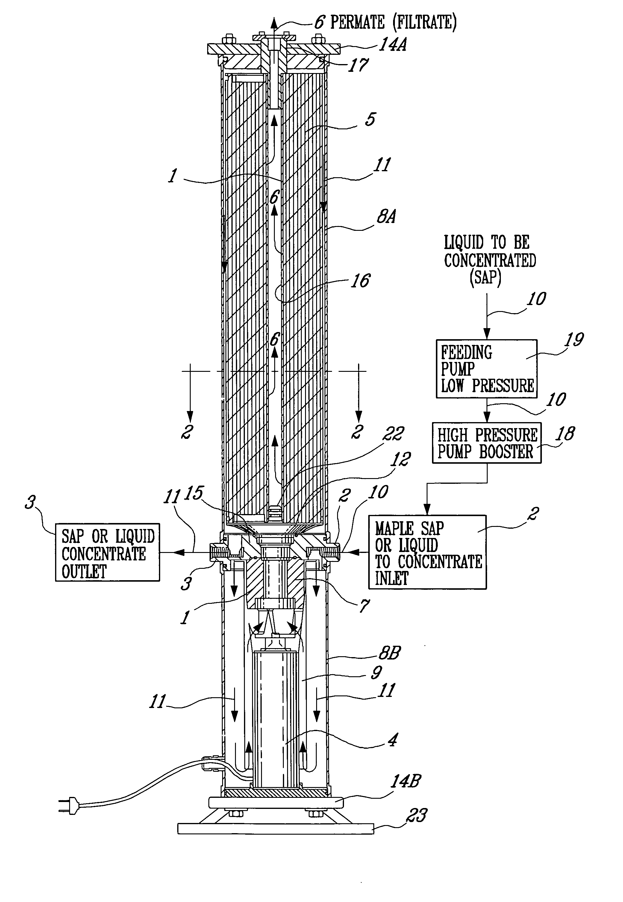
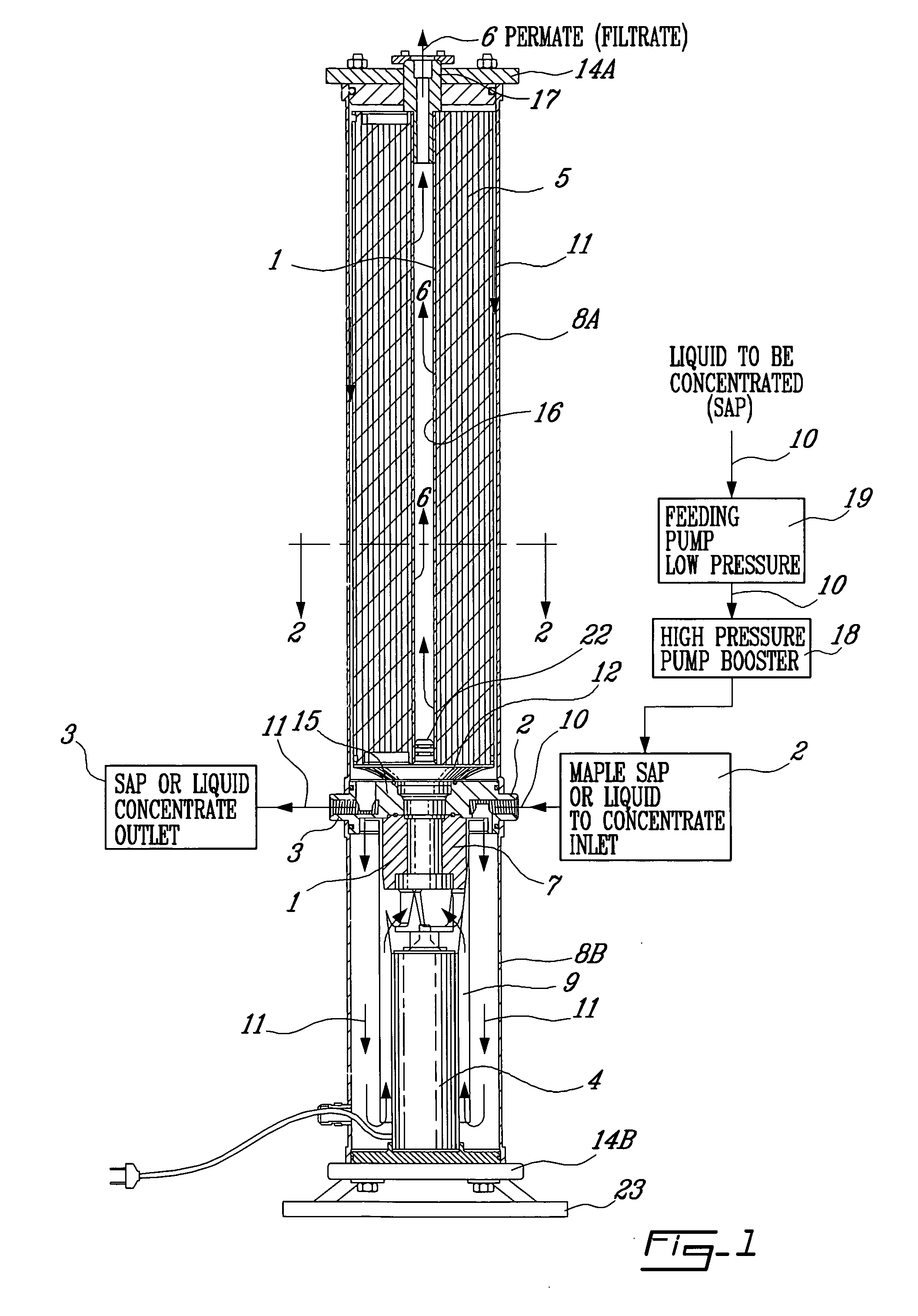
[0022] The present apparatus therefore consists in submersing a pump and its motor in one of the cylindrical vessels. The pump forces the mixture of concentrate and new liquid to be concentrated axially and with a cyclonic effect directly at one end of the membrane which is very close to the membrane. This provides an optimal efficiency of flow turbulence at those critical locations of bacteria formation and plugging during the concentration process.
[0023] This method of injecting a new mixture of liquid and concentrate in the membrane allows to maintain a positive pressure between the layers of the membrane which tend to open in order to remove the bacteria deposits or particles which slow down the reverse osmosis effect. Maximum flow created by the circulation pump thereby remains quasi constant at all times thus maintaining a self-cleaning effect during operation. Plugging is thereby reduced at its minimum.
[0024] The flow configuration of the present apparatus ensures at all times a maximum flow of the circulating pump independently of concentrations in the liquid to be concentrated in the membrane. A circulation in an opposite direction would affect the flow of the pump; indeed, a membrane which is plugged may be compared to a valve which gradually closes on the feeding side of the circulating pump. Therefore, a membrane completely plugged provides no circulation, cavities and heating of the pump impeller while accelerating the degradation of the concentrate.

Problems solved by technology

One major problem in concentrating maple sap or sweet liquids is the accumulation of bacteria in locations on the wire mesh support which are difficult to reach.

Method used


Image

  • Liquid separation apparatus
  • Liquid separation apparatus
  • Liquid separation apparatus

Examples


Embodiment Construction

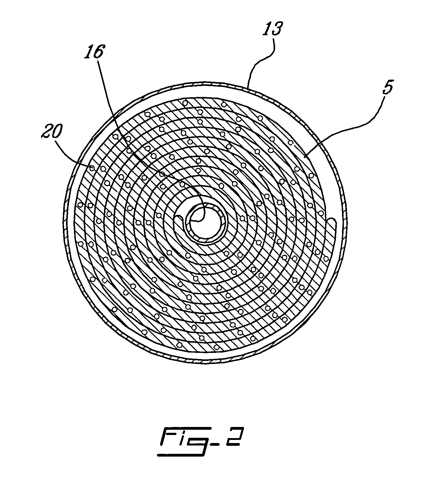
[0029] Referring to FIGS. 1 and 2, the liquid separation apparatus comprises a pair of watertight cylindrical vessels 8a and 8b which are closed at their opposite remote ends by caps 14a and 14b and at their common end by a dividing wall 15. A membrane 21 of synthetic fiber tissue is coiled onto a wire mesh grid 20 in vessel 8a. A pump 1 and its electric motor 4 are enclosed in vessel 8b. The motor 4 rotates the rotor 7 of the circulating pump 1. A feeding pump 19 of low pressure serves to inject liquid to be concentrated at the input of a high pressure booster pump 18 which, in turn, serves to maintain the pressure at an adequate value in vessels 8a and 8b in order to accelerate the reverse osmosis effect through the layers 5 of the membrane 21. A saucer plate 12 having an inverted cone shape and resting in liquid tight arrangement on the dividing wall 15 supports the membrane. The plate 12 has a central opening (not shown) in fluid communication with the upper end of the pump, thu...


PUM


Abstract

A two-vessel liquid separation apparatus includes a pump and its motor submersed in a one vessel and a reverse osmosis membrane in the other vessel. The vessels are separated by a contiguous dividing wall. The membrane and the pump are in fluid communication with one another through the dividing wall so as to allow liquid to pass from one vessel to the other in accordance with a given geometry. The pump receives liquid from the membrane containing vessel through holes in the dividing wall, the pump creating a highly turbulent flow caused by a cyclonic and co-axial effect, directly at the lower end of the membrane; the connexion of the pump outlet at the dividing wall is very close to the membrane thus providing an optimal efficiency of turbulence and flow at critical locations of bacteria collection. The injection of new liquid to be concentrated at the inlet of the pump causes an immediate mixture of liquid to be concentrated with concentrated liquid, which mixture circulates rapidly in a close circuit between the first and second vessels.

Description

FIELD OF THE INVENTION [0001] The invention relates to an apparatus for concentrating a liquid having materials in suspension (such as maple sap) by removing part of the water molecules therein in order to provide a concentrate ready for a subsequent operation, such as the evaporation of maple sap to obtain maple syrup as a finished product. BACKGROUND OF THE INVENTION [0002] In the field of maple sap evaporation, for example, the average sugar rate prior to concentration may vary between 1% and 6% depending on the type of maple tree or the region where this type of tree grows. The percentage of concentrate after concentration may vary up to 2 to 8 times the percentage of sugar in the original sap. [0003] Current maple sap concentration is between 8% and 10% prior to evaporation. The percentage of maple syrup sugar is 66% after evaporation. The usual energy required for this operation is derived from wood fire, oil heating or steam in a heat exchanger. Since it is required to reduce...

Claims


Application Information

Patent Timeline
IPC IPC(8): B01D63/00
CPCA23L1/09A23L2/085B01D61/025B01D61/08B01D2321/205B01D65/08B01D2313/243B01D2321/02B01D2321/10B01D63/10A23L29/30
Inventor CHABOT, JEAN-MARIE
Owner LES EQUIPS DERABLIERE CDL INC
Learn More