Apparatus and a method of soldering a part to a board

a technology of soldering apparatus and soldering parts, which is applied in the direction of soldering apparatus, manufacturing tools, electric/magnetic/electromagnetic heating, etc., and can solve the problems of parts not being fixed to the board, parts may overheat, and parts may not meet the requirements of the application

Active Publication Date: 2007-02-01
SENSBY +2
View PDF7 Cites 29 Cited by
  • Summary
  • Abstract
  • Description
  • Claims
  • Application Information

AI Technical Summary

Benefits of technology

[0014] An object of the present invention is to provide technology that can uniformly heat a plurality of solder material arranged in a plurality of locations on a board, and uniformly solder a plurality of parts arranged in a plurality of locations on the board.
[0017] In the present invention, a board, solder material, and parts are positioned inside an induction coil in which the distribution of the magnetic flux density is maintained so as to be relatively uniform other than outside of the induction coil. When an alternating current is conducted through the induction coil in this state, a uniform magnetic flux can be passed through the board and the solder material. When an alternating current is conducted through the induction coil when a board, solder material, and parts are arranged inside the induction coil, the plurality of solder material arranged in a plurality of positions on the board can be uniformly heated. As a result, the plurality of parts arranged in a plurality of locations on the board can be uniformly soldered to the board. Alternatively, the parts can be satisfactorily soldered to the board, even if a plurality of solder material is distributed to a plurality of locations on the board.
[0023] The soldering apparatus described above also provides the following effects. All of the magnetic flux that is generated by the induction coil will pass through the interior of the induction coil. Thus, the magnetic flux density generated by the induction coil will be higher inside the induction coil than outside the induction coil. In particular, the magnetic flux density will be high in the central region of the cross-section of the coil inner space. By positioning a board inside an induction coil in which the magnetic flux density is high (with the magnetic flux density being particular high in the central region of the cross-section thereof), solder material on the board may be heated with good efficiency. A heating efficiency can be obtained that is higher than when a board is positioned on the outside of an induction coil, as with the conventional technology.

Problems solved by technology

When the temperature is too high, the circuit parts may overheat, and the capabilities thereof may be degraded.
When the temperature is too low, the solder material may not melt, and a part may not be fixed to the board.
When the solder material is placed in a location in which the magnetic flux density is high, the solder material may overheat.
When the solder material is placed in a location, in which the magnetic flux density is low, the solder material may be heated to an insufficient temperature.
With conventional soldering apparatus, it may be difficult to uniformly heat a plurality of solder material arranged in a plurality of locations on a board.
In addition, it may be difficult to satisfactorily solder a plurality of types of devices in which the solder material is arranged in different positions on the board.

Method used


Image

  • Apparatus and a method of soldering a part to a board
  • Apparatus and a method of soldering a part to a board
  • Apparatus and a method of soldering a part to a board

Examples


embodiment 1

[0065] Preferable embodiments will described below with referring drawings.

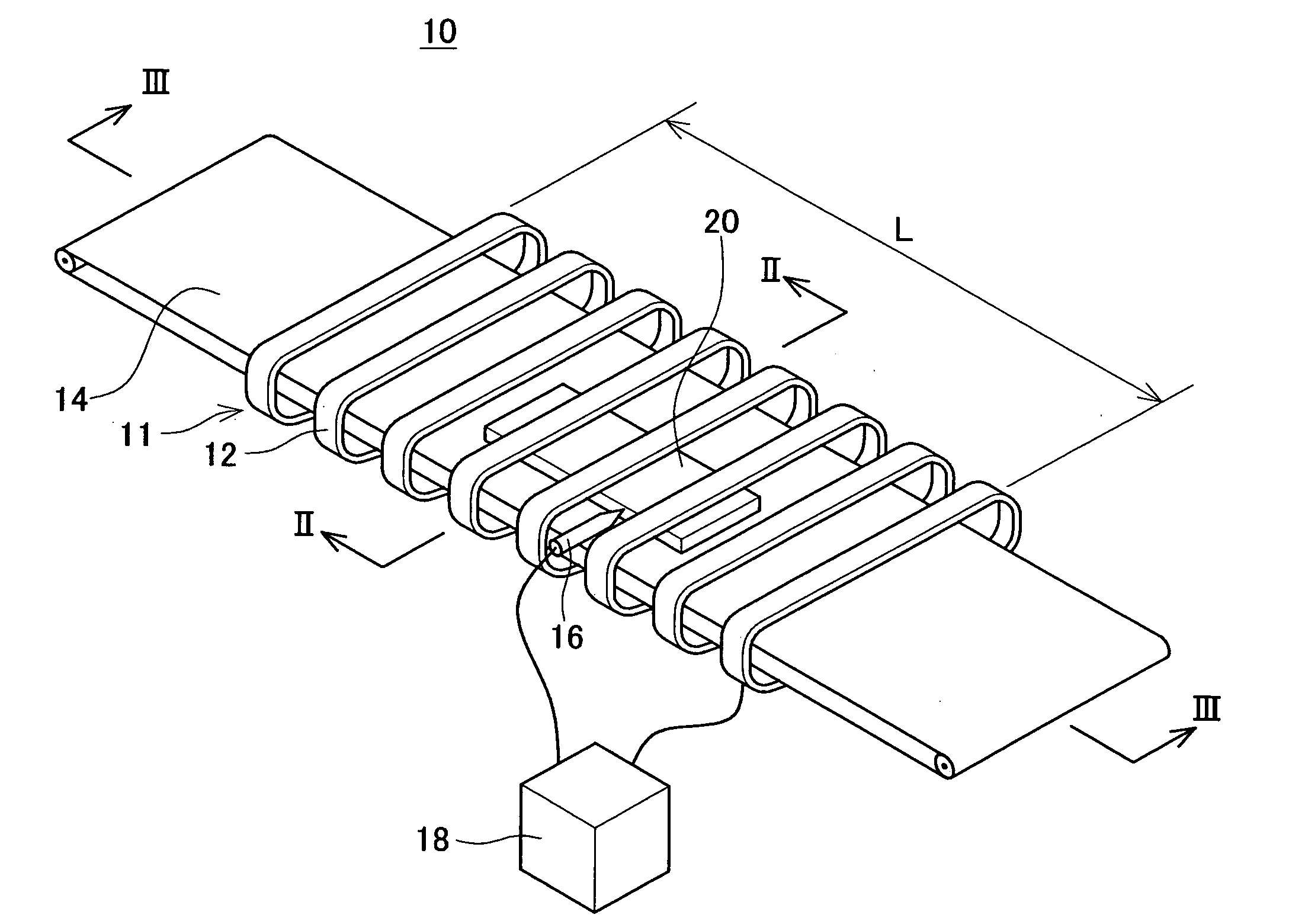
[0066]FIG. 1 shows first embodiment of the soldering machine 10 according to the present invention. The soldering machine 10 comprises a conveyor 14 (corresponding to a positioning device recited in claims) that conveys a board supporting circuit parts via solder material in a solid state, an induction coil 11 that surrounds the middle of the conveyor 14, a temperature sensor 16 that measures the temperature of the board, and a controller 18 that controls those units. The controller 18 applies alternating current to the induction coil 11. The induction coil 11 is formed by winding a winding 12 into a helical shape.

[0067] Hereinafter, a board that includes a circuit part and solder material will be referred to as work piece 20. The circuit part, solder material, and board are not individually illustrated in FIG. 1 but illustrated in FIG. 2. The induction coil 11 is drawn in FIG. 1 as it is formed by winding ...

embodiment 2

[0100] Next, a method of manufacturing a device having a board on which circuit parts are soldered will be described. In the present embodiment, the device is a circuit board having predetermined functions.

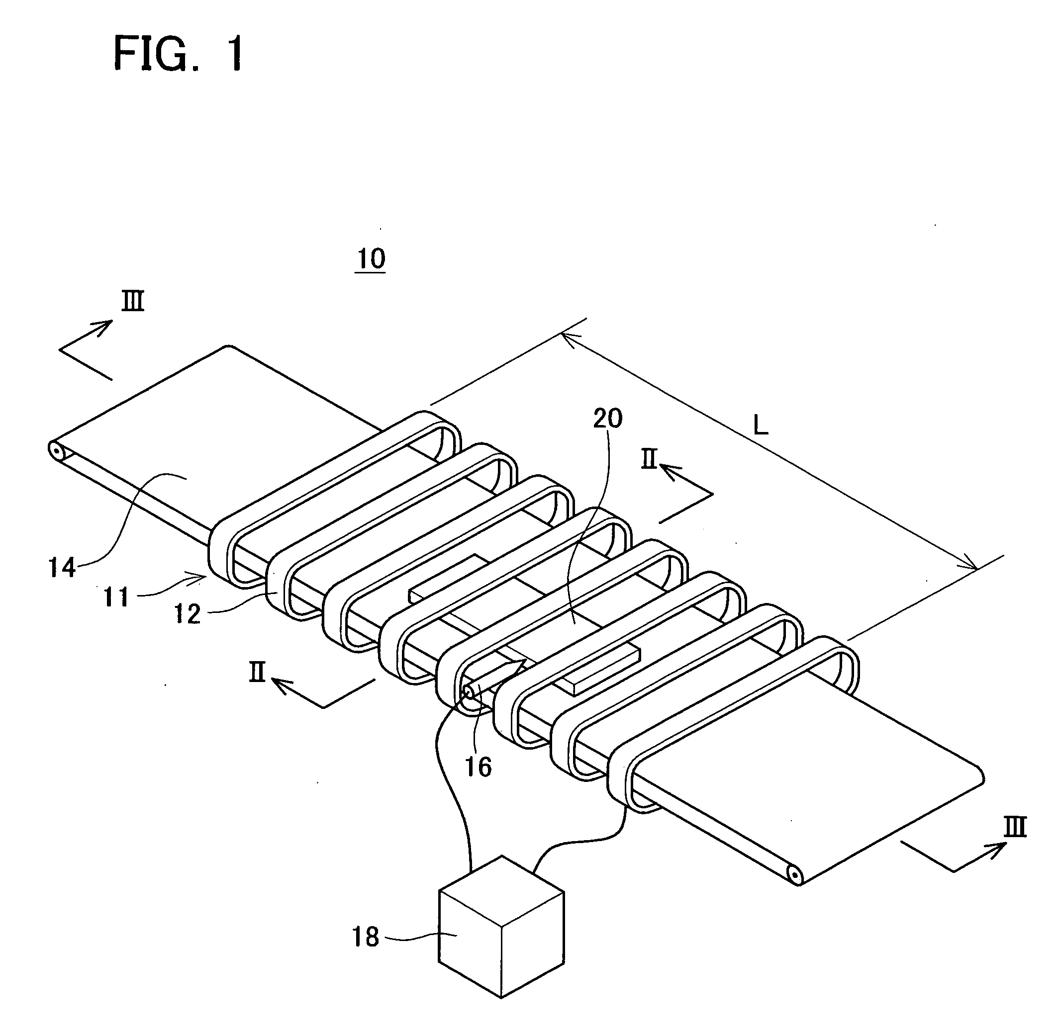
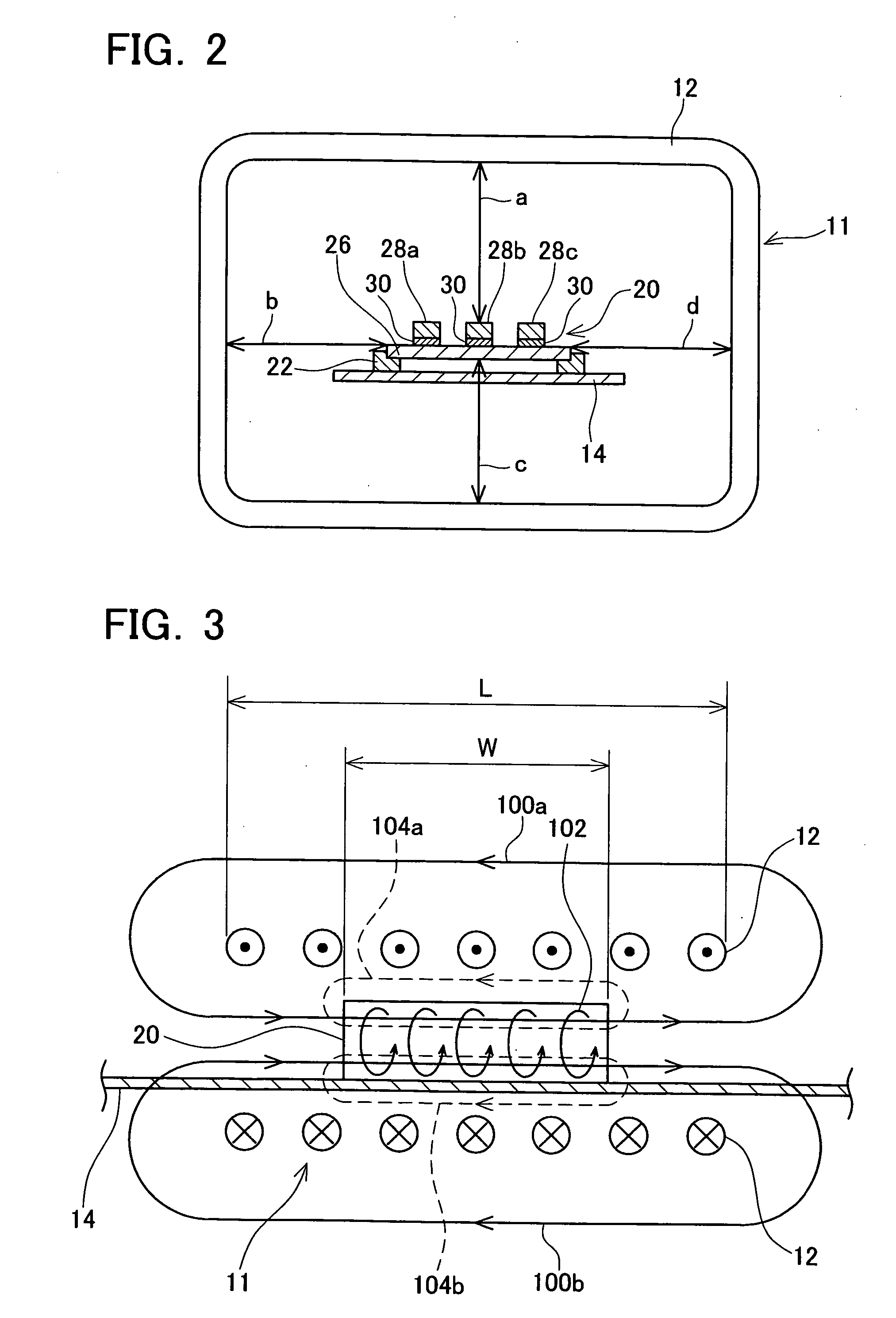
[0101] In the manufacturing process, the circuit board, such as the board 26 shown in FIG. 2, is first positioned in the central region of the cross-section of the inner space of the induction coil 11, as shown in FIGS. 1 and 2. At this point, circuit parts 28a, 28b, 28c and solid solder material 30 are mounted on the board 26. Then, an alternating current will be made to pass through the induction coil 11 by the controller 18. By making an alternating current pass through the induction coil 11, an alternating magnetic field may be generated in the induction coil 11. Due to the induction heating effect of the alternating magnetic field, the solder material 30 on the board 26 may be heated and melted. At the point at which the solder material 30 has melted, the flow of the alterna...


PUM

PropertyMeasurementUnit
lengthaaaaaaaaaa
areasaaaaaaaaaa
magnetic fieldaaaaaaaaaa

Abstract

The present invention provides technology that uniformly heats and melts a plurality of solder material arranged in a plurality of locations on a board, and uniformly solders a plurality of parts to the board that are arranged in a plurality of locations on the board. A soldering apparatus includes an induction coil having a length in the longitudinal direction that is longer than the length of the board. An inner space having a size sufficient to arrange the board therein is maintained inside the induction coil. The board supporting the parts and the solder material will be positioned in the approximate center of the inner space of the induction coil. An alternating current will flow through the induction coil in this state. An alternating magnetic field will be generated in the inner space of the induction coil. Magnetic fluxes will substantially uniformly pass through the inner space of the induction coil along the longitudinal direction of the induction coil. In this way, the plurality of solder material arranged on a plurality of locations on the board may be uniformly heated and melted. The plurality of parts arranged on a plurality of locations on the board may be uniformly soldered to the board because the plurality of solder material may be uniformly heated and melted due to magnetic fluxes that uniformly passing through the board.

Description

CROSS REFERENCE TO RELATED APPLICATION [0001] This application claims priority to Japanese Patent Application No. 2005-220746 filed on Jul. 29, 2005, the contents of which are hereby incorporated by reference into the present application. BACKGROUND OF THE INVENTION [0002] 1. Field of the Invention [0003] The present invention relates to an apparatus and a method of soldering parts such as electronic parts to a board such as a circuit board. [0004] 2. Description of the Related Art [0005] Technology for manufacturing an electronic device by soldering electronic parts to a board on the surface of which circuit patterns are formed is known. In this situation, the solder material is employed in order to mechanically fix the electronic parts to the board, and ensure electrical conduction between the circuit patterns formed on the surface of the board and the electronic parts. The solder material is very useful in order to ensure electrical conduction while mechanically fixing the electr...

Claims


Application Information

Patent Timeline
Patent Type & Authority Applications(United States)
IPC IPC(8): B23K31/02
CPCB23K1/002B23K2201/42H01L2224/81222H01L2924/01068H05K2203/101H01L2924/01019H05K3/3494B23K2101/42H01L2224/75264H01L2224/83222H01L2224/83801
Inventor MATSUURA, MASANARIKOIZUMI, MASAHIROTSURUTA, MASAYAKUBOTA, TOMOYUKINAKAMURA, YOSHIYUKI
Owner SENSBY
Why Eureka
Try Eureka