High voltage design structure for high temperature superconducting device

a design structure and high-temperature superconducting technology, applied in the direction of superconducting magnets/coils, magnetic bodies, instruments, etc., can solve the problems of not being able to use cryogenic dielectric systems as viable insulation systems for high-voltage applications, the design of high-voltage devices becomes a challenge, and the cryogenic dielectric system is not yet well understood as a viable insulation system for high-voltage applications

Inactive Publication Date: 2007-02-01
SUPERPOWER INC
View PDF4 Cites 8 Cited by
  • Summary
  • Abstract
  • Description
  • Claims
  • Application Information

AI Technical Summary

Benefits of technology

[0008] Briefly, in accordance with the present invention, modular corona shields, or also referred to as Stress Shields, are employed in a high temperature superconductor system to reduce the electric field surrounding the assembly of high temperature superconducting elements and associated components, known as the High Temperature Superconducting (HTS) device. In an exemplary embodiment a high temperature HTS system has at least one HTS device in the insulation region of a cryogenic cooling system which employs a first corona shield disposed along the top portion of the HTS device and is electrically coupled to the HTS device. A second corona shield is disposed along the bottom portion of the HTS device and is electrically coupled to the HTS device. An insulation barrier is disposed within the insulation region along at least one side of the HTS device. The first corona shield and the second corona shield act together to reduce the electric field stress surrounding the HTS device when energized at high voltage.

Problems solved by technology

As the need for higher power and higher voltage applications of Superconducting devices increases, designing high voltage devices in a cryogenics dielectric environment becomes a challenge.
The cryogenic dielectric systems are not yet well understood as viable insulation systems for high voltage applications.
Conventional high voltage devices such as high voltage cables have employed corona shields to control electrical field stress, however, electrical corona shield solutions have not been employed in a cryogenic environment
This patent does not teach or disclose the use of a corona shield in a cryogenic environment.

Method used


Image

  • High voltage design structure for high temperature superconducting device
  • High voltage design structure for high temperature superconducting device
  • High voltage design structure for high temperature superconducting device

Examples


Embodiment Construction

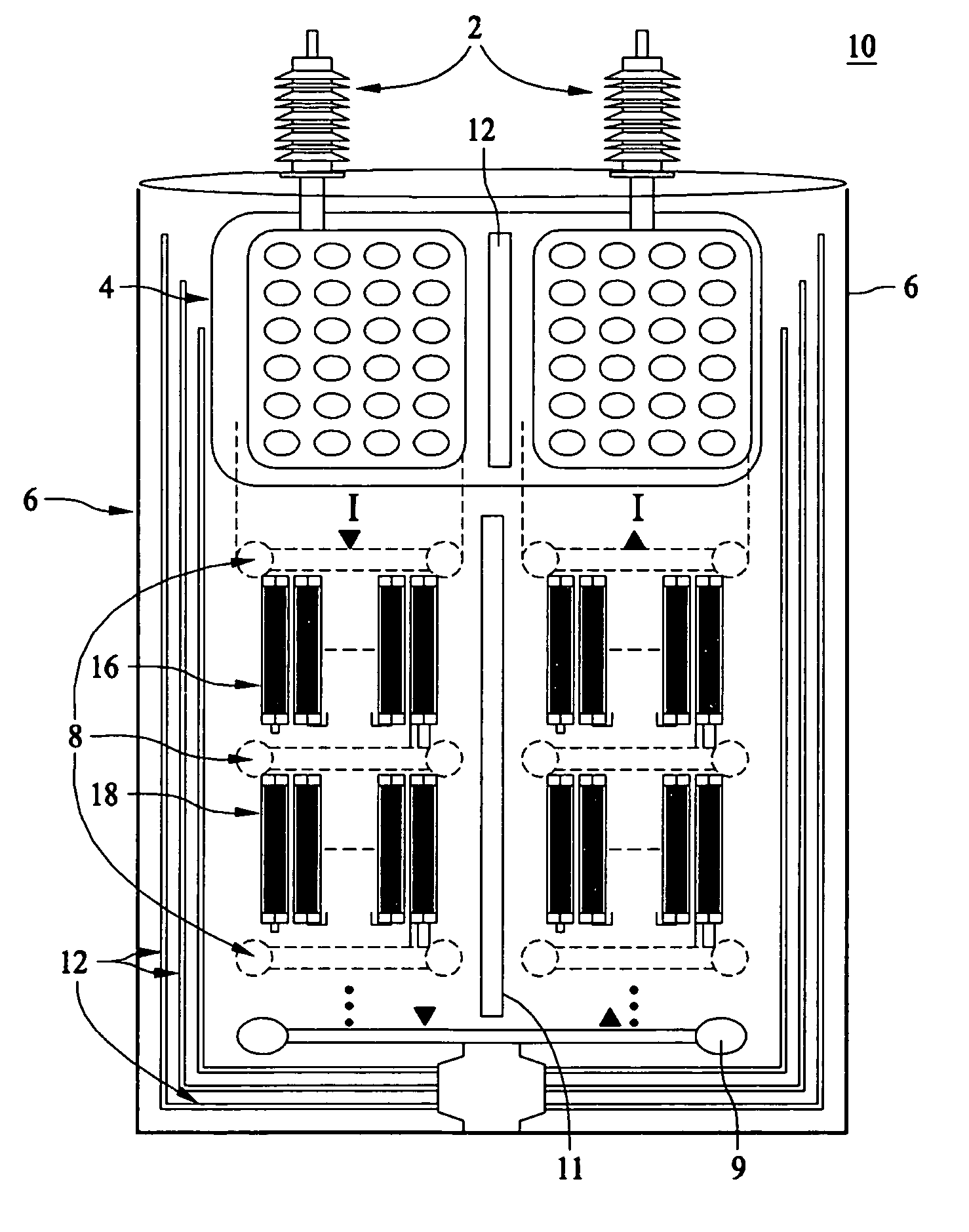
[0016] The invention addresses the high voltage design challenges within a cryogenic dielectric medium. The invention uses a high voltage design that improves the dielectric performance to reduce the electric field stress in all parts of the insulation regions by using corona shields and by using solid insulators to partition the gas or liquid dielectric regions.

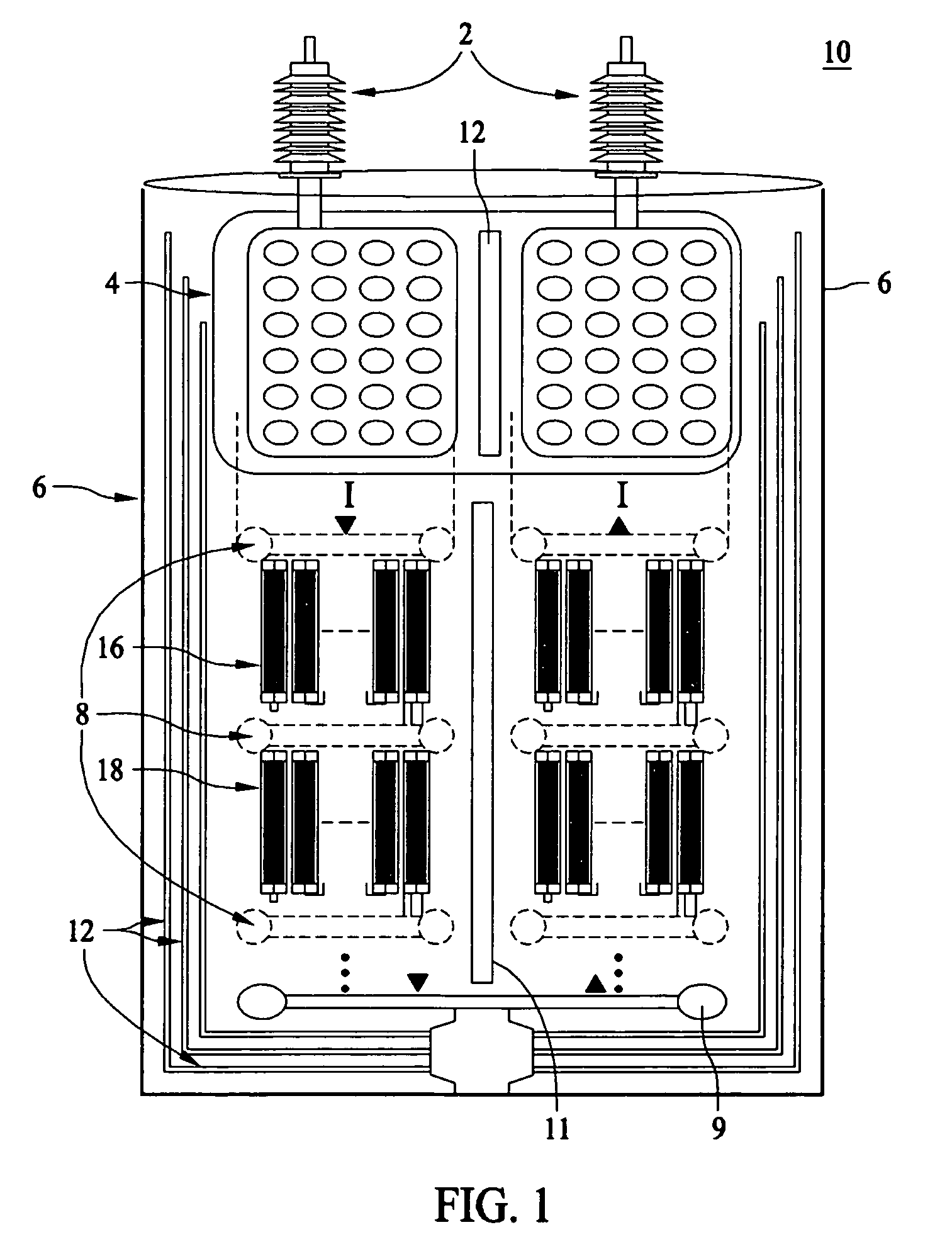
[0017]FIG. 1 illustrates the layout of corona shields in a high voltage fault current limiter system 10 of the present invention. A first corona shield 8 is disposed along the top portion of a FCL set 16 and is electrically coupled to the FCL set 16. A second corona shield 8 is disposed along the bottom portion of the FCL set 16 and is electrically coupled to the FCL set 16. The arrangement of the FCL set 16 and the two corona shields is a first fault current limiter module (FCLM). FCL set 16 comprises at least one fault current limiter, and in a preferred embodiment a plurality of fault current limiters. The second corona ...


PUM


Abstract

In accordance with the present invention, modular corona shields are employed in a HTS device to reduce the electric field surrounding the HTS device. In a exemplary embodiment a fault current limiter module in the insulation region of a cryogenic cooling system has at least one fault current limiter set which employs a first corona shield disposed along the top portion of the fault current limiter set and is electrically coupled to the fault current limiter set. A second corona shield is disposed along the bottom portion of the fault current limiter set and is electrically coupled to the fault current limiter set. An insulation barrier is disposed within the insulation region along at least one side of the fault current limiter set. The first corona shield and the second corona shield act together to reduce the electric field surrounding the fault limiter set when voltage is applied to the fault limiter set.

Description

CROSS REFERENCE TO RELATED APPLICATIONS [0001] This US non-provisional application claims the benefit of U.S. provisional Patent Application, Ser. No. 60 / 694,217 entitled “High Voltage Design Structure For High Temperature Superconducting Device,” filed on Jun. 27, 2005, having at least one co-inventor in common with this application.LICENSE [0002] The U.S. government has a paid-up license in this invention and the right in limited circumstances to require to the patent owner to license others on reasonable terms as provided for in the terms of Contract No. DE-FC36-03G013033 awarded by the Department of Energy and Contract No. EP-P 10361 / C5273.BACKGROUND [0003] The invention relates generally to a cryogenic dielectric environment for high temperature superconductor (HTS) devices and more particularly to high voltage structures in a cryogenic dielectric environment for an electrical power system. [0004] As the need for higher power and higher voltage applications of Superconducting d...

Claims


Application Information

Patent Timeline
Patent Type & Authority Applications(United States)
IPC IPC(8): H01J27/00
CPCH01L39/16H01F2006/001Y10S505/885Y10S505/883Y10S505/85Y10S505/875H10N60/30
Inventor TEKLETSADIK, KASEGN D.
Owner SUPERPOWER INC
Why Eureka
Try Eureka