Switch device

A technology of switchgear and open circuit state, which is applied in the direction of switchgear, switchgear setting, switchgear with metal casing, etc., which can solve the problems of large size, poor insulation performance and arc extinguishing performance, and cost increase.

Inactive Publication Date: 2004-01-28
HITACHI LTD
View PDF1 Cites 9 Cited by
  • Summary
  • Abstract
  • Description
  • Claims
  • Application Information

AI Technical Summary

Problems solved by technology

The insulating performance and arc extinguishing performance of these gases are due to the ratio of SF 6 Gas is poor, so there is

Method used


Image

  • Switch device
  • Switch device
  • Switch device

Examples


Embodiment Construction

[0018] Embodiments of the present invention will be described below with reference to the accompanying drawings.

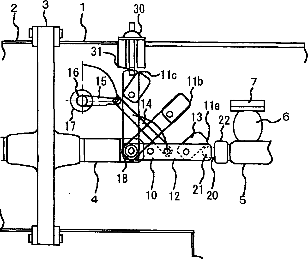
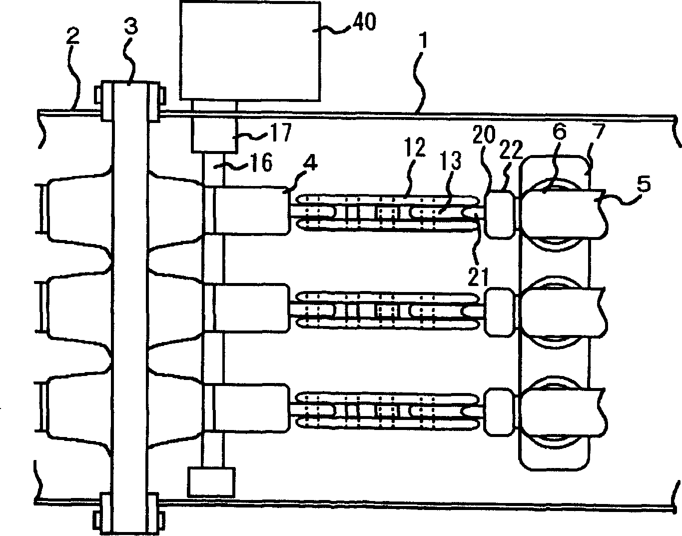
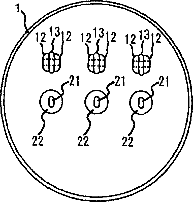
[0019] figure 1 It is an embodiment of a circuit breaker with a grounding device to which the switchgear of the present invention is applied. figure 2 for viewing from below figure 1 The circuit diagram of is an example of arranging three phases at a time in grounded metal containers 1 and 2. Nitrogen gas is sealed in the grounded metal containers 1 and 2, and each component is separated by an insulating blocking plate 3. The enclosed gas can also be dry air, carbon dioxide and other gases, or SF 6 gas, C 3 f 8 , c-C 4 f 8 Such as Freon gas, and their mixed gas with nitrogen, or mixed gas with dry air. In the grounded metal containers 1, 2, the high voltage conductors 4, 5 are insulated and supported by insulating blocking plates 3, blocking columns 6, and the like. The blocking column 6 is fixed on a base 7 provided on the grounded metal container 1 . ...


PUM


Abstract

In this switching device, a field relaxation electrode is provided on the movable contact of a disconnector so that the movable contact can be connected to a fixed contact by changing the position of the field relaxation electrode between an open state and a closed state. By providing the field relaxation electrode on the movable contact of the disconnector, the ground dielectric strength and interpolar dielectric strength in the open state position can be improved to reduce the size and cost of the equipment. By improving the charging current interrupting performance and exciting current interrupting performance, the applicable range on system of the equipment can be extended.

Description

technical field [0001] The invention relates to a switchgear suitable for substations, switching stations, substations for power distribution, etc. of civil ultra-high input power transformation equipment or power systems. Background technique [0002] In the prior art, such as the gas insulated switchgear of Japanese Patent Application Laid-Open No. 10-155215, in a circuit breaker, a knife-shaped movable contact rotates around the rotating shaft of the movable side conductor, and moves from and to The closed circuit position of the fixed contact connection is the open circuit position when the rotary lever is turned 45 degrees, and the position where it is turned 45 degrees is the grounding position, which becomes a structure connected to the grounding terminal, constituting a circuit breaker with a grounding device. [0003] In recent years, with the trend of easing international regulations on electric power business, there has been an increasing demand for substantial co...

Claims


Application Information

Patent Timeline
IPC IPC(8): H02B13/00H01H31/02H01H31/28H02B13/02H02B13/055H02B13/075
CPCH02B13/035H02B13/02H02B13/00
Inventor 内海知明遠藤奎將六戶敏昭中野幸一大森莊司八木橋義豊
Owner HITACHI LTD
Why Eureka
Try Eureka