Electric machine with rotor cooling and corresponding cooling method

a technology of rotor cooling and electric machines, which is applied in the direction of cooling/ventilation arrangement, magnetic circuit rotating parts, magnetic circuit shape/form/construction, etc., can solve the problems of high complexity of the type of contra-direction cooling, and achieve the effect of no high production cost of the rotor pressure ring, improved cooling effect, and uniform cooling of the rotor

Active Publication Date: 2007-02-01
SIEMENS AG
View PDF12 Cites 52 Cited by
  • Summary
  • Abstract
  • Description
  • Claims
  • Application Information

AI Technical Summary

Benefits of technology

[0007] Advantageously, a separation of the air inlet holes from the air outlet holes of the rotor cooling routing in the case of contradirectional cooling can consequently be achieved in a relatively cost-effective way. To be precise, the rotor pressure ring or rotor pressure rings may be integrated into the air routing device.
[0008] Preferably, the axial bores are combined into a plurality of groups by means of at least one of the two rotor pressure rings, so that the coolant stream through the bores of each group is essentially identical. By the individual bores being grouped together, the coolant flow is improved. For example, in each case two, three or four bores, but even more, if desired, can be combined in each group.
[0009] Furthermore, the targeted coolant routing may be configured such that the bores or groups of bores are cooled contradirectionally with respect to one another. This leads to a more uniform cooling of the rotor in the axial direction.
[0010] Furthermore, radii for improving the coolant flow are formed, in particula

Problems solved by technology

However, this type of contradirecti

Method used


Image

  • Electric machine with rotor cooling and corresponding cooling method
  • Electric machine with rotor cooling and corresponding cooling method
  • Electric machine with rotor cooling and corresponding cooling method

Examples


Embodiment Construction

[0022] The exemplary embodiments described in more detail below constitute preferred embodiments of the present invention.

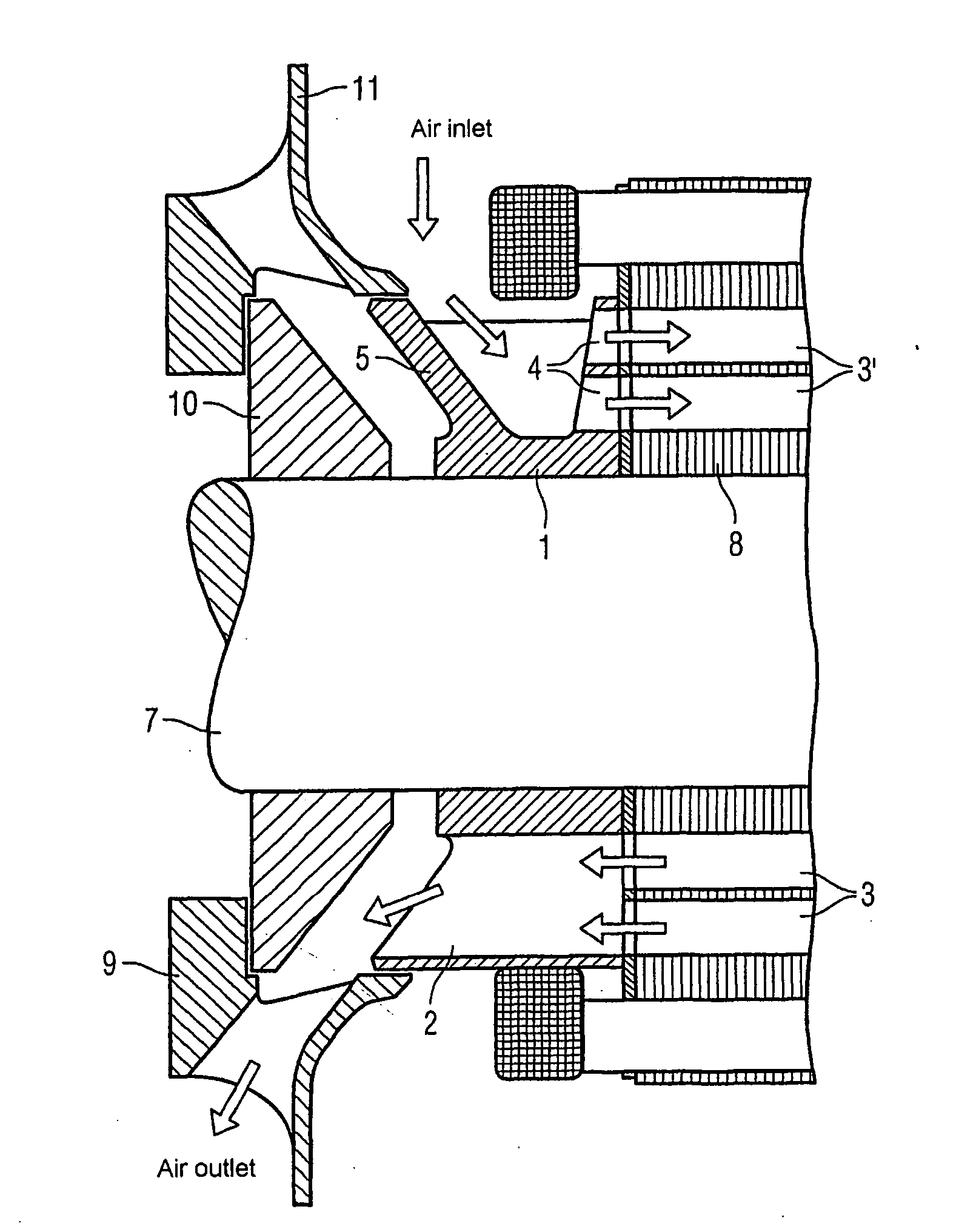
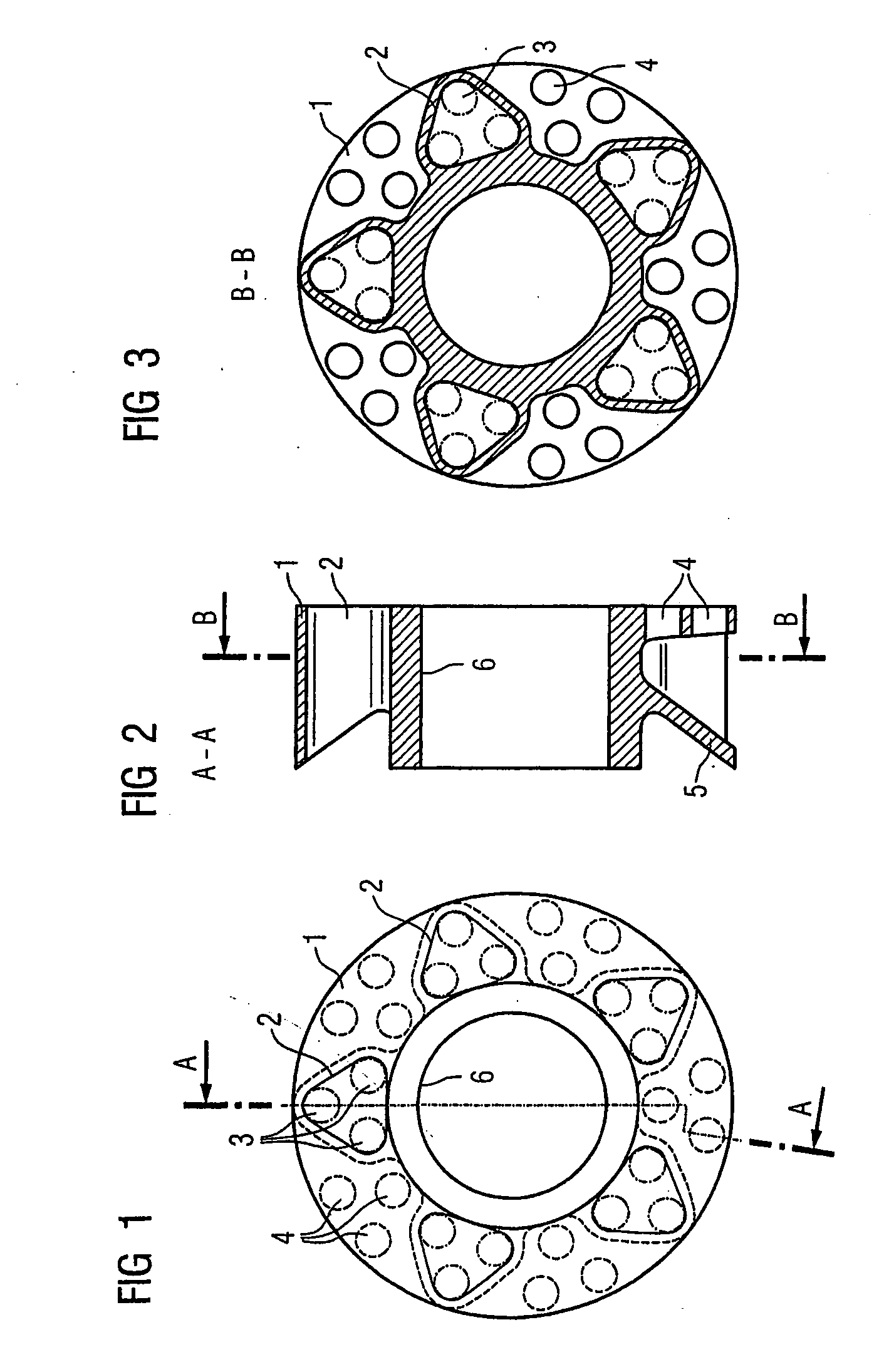
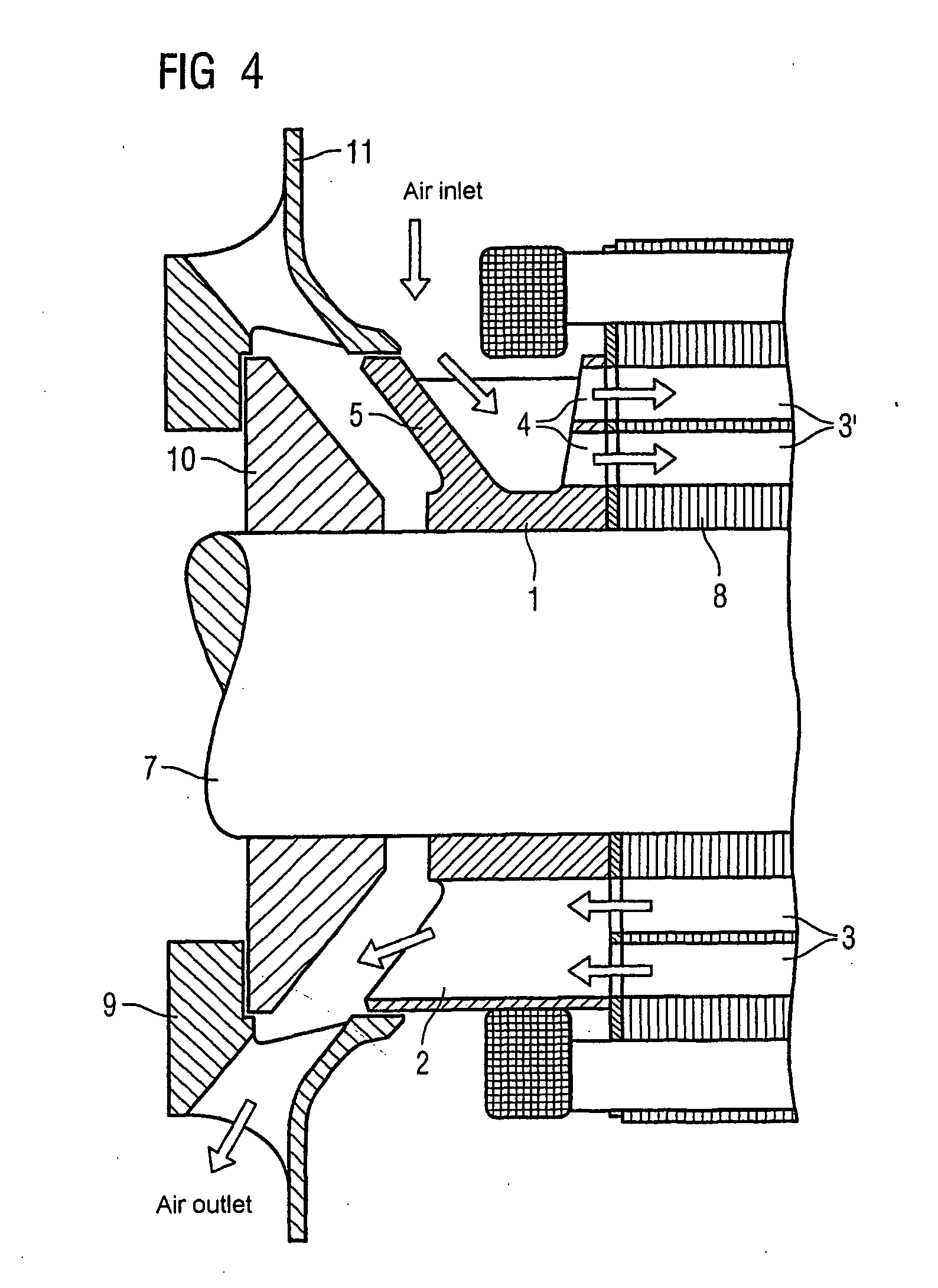
[0023] According to the invention, the rotor pressure ring possesses an additional functionality, to be precise that of routing the coolant through the axial bores of the rotor. A correspondingly configured rotor pressure ring 1 is illustrated in a top view in FIG. 1. Five triangular coolant leadthroughs 2 are arranged on its circumference. In each case three bores 3 are indicated in these coolant passages 2 by a dashed and dotted line and are located in a rotor, not illustrated, arranged behind the rotor pressure ring 1. Thus, by means of the triangular leadthrough 2, in each three holes or bores 3 are combined into a group of holes.

[0024]FIG. 2 illustrates the coolant leadthrough 2 in cross section. It is evident from this, furthermore that the contour of the coolant leadthrough 2 runs obliquely in the radial direction. The reason for this is that, owing to f...


PUM


Abstract

The aim of the invention is to optimize cooling of a rotor using simple means. A rotor is provided, comprising rotor pressure rings (1) such that at least one of the two rotor pressure rings (1) is configured in order to enable targeted guiding of the coolant through the axial bores (3, 3′) in the rotor. In a special embodiment, the rotor pressure ring (1) can be formed in such a manner that it produces, in several bores (3′) in the rotor sheet stack (8), a flow of coolant in a first direction and in other bores (3), a flow of coolant in the other direction. An even, opposite flow cooling can be exclusively obtained by the contour of the rotor pressure ring (1).

Description

BACKGROUND OF THE INVENTION [0001] The present invention relates to a rotor device with a laminated core arrangement, which has a plurality of axial bores for the conduction of a coolant, and with two rotor pressure rings, between which the laminated core arrangement is fixed axially. The present invention relates, furthermore, to an electric machine having a rotor device of this type and to a corresponding method for cooling a rotor device. [0002] Where electric machines of higher power are concerned, rotor cooling is often necessary. A corresponding electric machine is known, for example, from the document U.S. Pat. No. 2,610,992. The stator and rotor laminated cores described there have air cooling ducts running axially. [0003] In order to execute ventilation more uniformly in the axial direction, ventilation of the rotor on both sides may be provided. The German laid-open publication DE 44 13 389 describes, for example, such an electric machine. It possesses two rotor laminated ...

Claims


Application Information

Patent Timeline
IPC IPC(8): H02K9/00H02K1/32H02K9/06
CPCH02K9/06H02K1/32H02K1/265H02K15/024
Inventor SCHMIDT, VALERIAS
Owner SIEMENS AG
Why Eureka
Try Eureka