Line head and image-forming apparatus

a line head and image-forming technology, applied in the field of line head and image-forming apparatus, can solve the problems of shortening the life of each of the organic el devices, difficult to sufficiently expose the photosensitive drum, and relatively low light brightness, so as to achieve reliable light exposure, reduce the effect of light intensity and efficient removal

Inactive Publication Date: 2007-02-01
SEIKO EPSON CORP
View PDF7 Cites 6 Cited by
  • Summary
  • Abstract
  • Description
  • Claims
  • Application Information

AI Technical Summary

Benefits of technology

[0008] An advantage of some aspects of the invention is to provide a line head capable of lengthening the life of each organic EL device serving as a light emitting device and capable of having high brightness (i.e., high light intensity), and provide an image-forming apparatus including the line head.
[0010] In the line head, light emitted from organic electroluminescent devices is reflected by the reflective film provided on the second substrate, is then guided through the optically transparent bonding layer, is then concentrated on the exit portion, and is passed out toward the outside. Since light obtained by concentrating the light emitted from organic electroluminescent devices is exit from each of the exit portions in this way, the light exited from each of the exit portion has high intensity (high brightness). If the size of the emitting area of the organic electroluminescent devices is enlarged without changing the size of the exit portion, the amount of light emitted from the organic electroluminescent devices is increased, and hence light having a higher intensity can be passed out from the exit portion. The photosensitive drum can be reliably exposed by using the line head capable of emitting light having high intensity. Since light having high intensity can be passed out without passing a large amount of electric current through such a small-sized organic electroluminescent device, the organic electroluminescent device is never deteriorated by heat. Thus, according to the line head, the life of the organic electroluminescent device can be lengthened, and light having high intensity can be passed out.
[0011] Preferably, in the line head, the second substrate faces an emission side of the first substrate. Accordingly, light emitted from the organic electroluminescent devices pass through the bonding layer, and is guided by the reflective film. Therefore, the light is never attenuated by a substrate through which light emitted from the organic electroluminescent device passes before being reflected unlike a case in which the reflection substrate is caused to adhere to the opposite side of the substrate. Therefore, light having high intensity can be obtained by efficiently passing out light from the exit portion.
[0015] The line head may include a plurality of microlenses each of which corresponds to each of the exit portions. In this case, the line head may include a head base having the first substrate, the bonding layer, and the second substrate; and a microlens array substrate having the microlenses and bonded to the head base. In this line head, light exited from the exit portion can be concentrated by the microlens, and can be efficiently taken out toward the outside, and hence the intensity of the light can be heightened more.
[0016] According to a second aspect of the invention, there is provided an image-forming apparatus is characterized by including the line head mentioned above and a photosensitive drum exposed to the line head. In the image-forming apparatus, the line head having high light intensity is used as an exposure means, and hence the photosensitive drum can be reliably exposed to light, and a correct image can be formed.

Problems solved by technology

In the line head disclosed in JP 2005-119104, relatively expanded light is projected from the organic EL devices onto a photosensitive drum, and hence the light becomes relatively low in brightness (i.e., in intensity), thus making it difficult to sufficiently expose the photosensitive drum.
However, according to this method, high heat is generated in the organic EL devices in accordance with the amount of the electric current, and deteriorates the organic EL devices used as light emitting devices, thus shortening the life of each of the organic EL devices.

Method used


Image

  • Line head and image-forming apparatus
  • Line head and image-forming apparatus
  • Line head and image-forming apparatus

Examples


first embodiment

[0031] A first embodiment of a line head will be first described. The line head is used as an exposure means of an image-forming apparatus described later. In more detail, the line head is used in the state of a line head module including the line head.

[0032] Line Head Module

[0033] First, a description will be given of a line head module used as an exposure means of an image-forming apparatus.

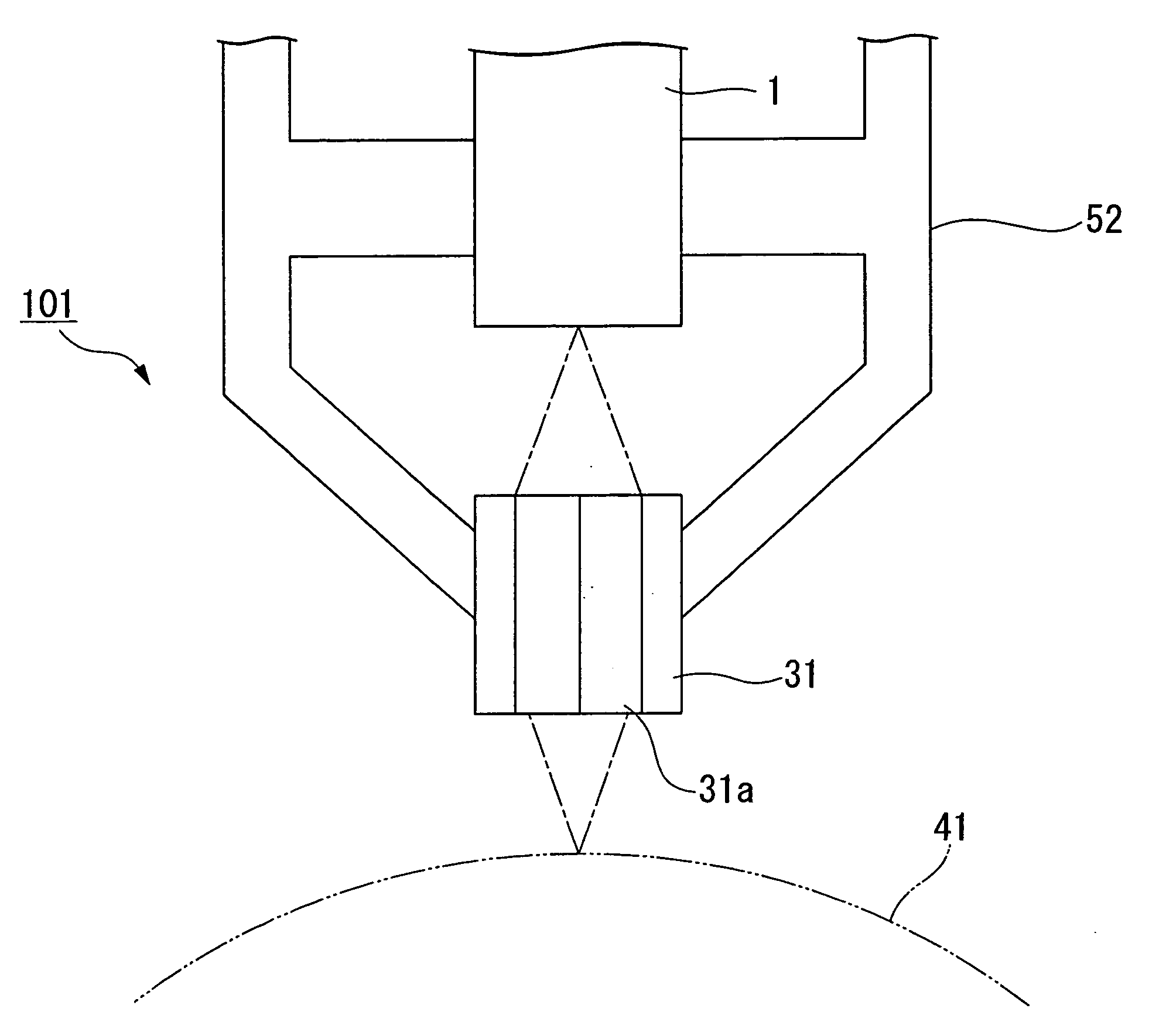
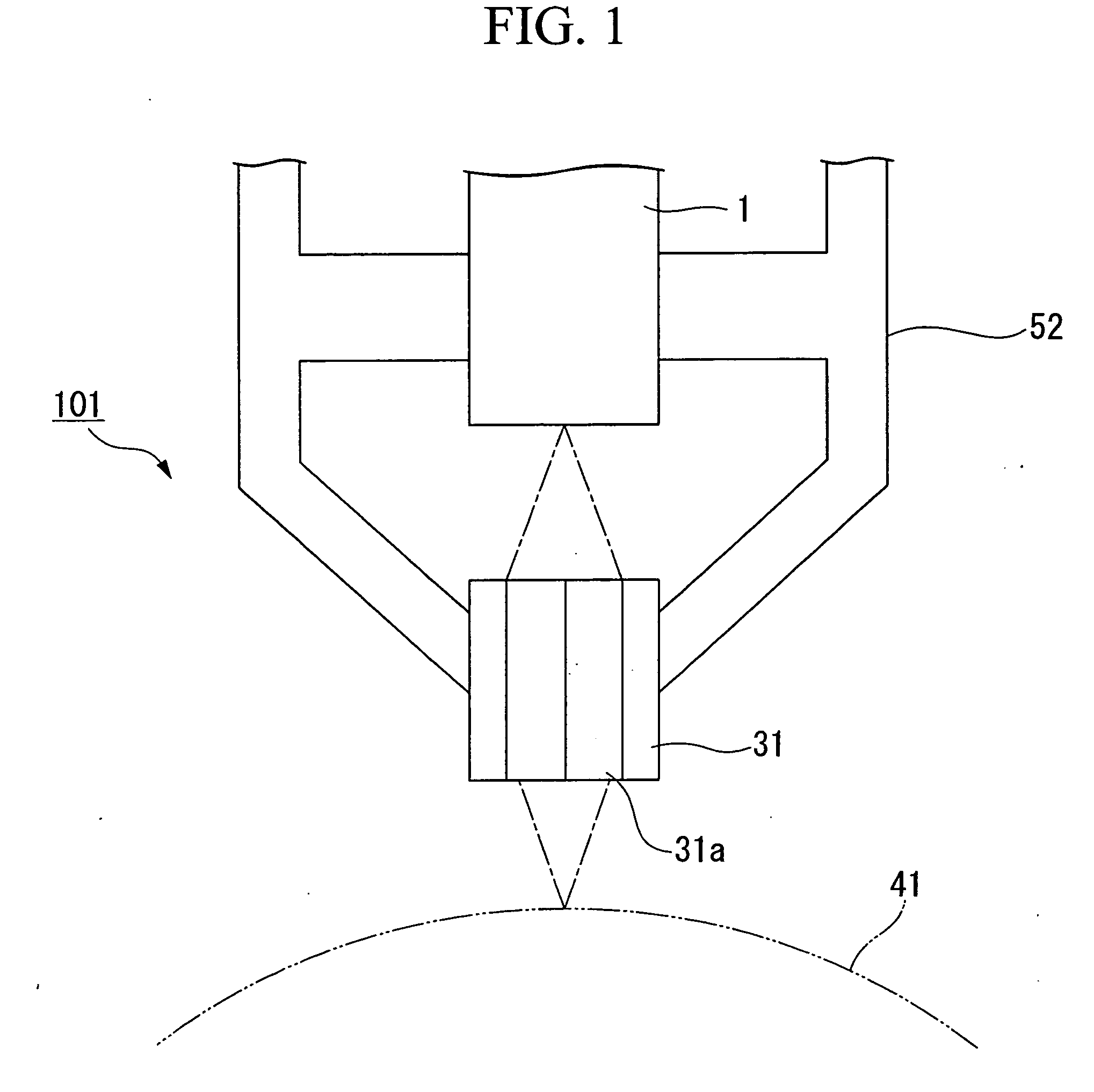
[0034]FIG. 1 is a sectional side view of the line head module. As shown in FIG. 1, a line head module 101 according to this embodiment includes a line head 1 that has a plurality of organic EL devices (electroluminescence devices) arranged in orderly rows, an SL array (Selfoc Lens Array) 31 that has a plurality of SL devices 31a arranged in orderly rows, and a head case 52 to which the line head 1 and the SL array 31 are fixed. The SL device 31a allows light emitted from the line head 1 to form an upright same-size image. In the line head module 101, light emitted from the organic EL devices...

second embodiment

[0109] Next, a second embodiment of the line head of the present invention will be described.

[0110] As shown in FIG. 10A and FIG. 10B, a line head 1′ according to this embodiment includes a microlens array substrate MA that has a plurality of microlenses M on the side of the end surface of the head base 7. In this embodiment, the structure of the line head 1′ excluding the microlens M is the same as that of the microlens M according to the first embodiment. In the following description, the same reference characters are given to the same structures as in the first embodiment, and a description of the same structures is omitted.

[0111] The microlens array substrate MA is formed with a glass substrate, and has a plurality of microlenses M each of which corresponds to each of the exit portions 12, as shown in FIG. 10A and FIG. 10B.

[0112] Each microlens M is aligned with each exit portion 12, and is caused to adhere to the head base 7 with an bonding layer 8′ having optical transparen...


PUM


Abstract

A line head includes: a first substrate having a plurality of organic electroluminescent devices; a bonding layer disposed on the first substrate and having optical transparency; a second substrate bonded to the first substrate with the bonding layer therebetween and having a reflective film that covers at least a part of the bonding layer; and a plurality of exit portions respectively from which light that has passed through the bonding layer is exited, the light emitted from the organic electroluminescent devices.

Description

CROSS-REFERENCE TO RELATED APPLICATION [0001] This application claims priority to Japanese Patent Application No. 2005-215529, filed Jul. 26, 2005, the contents of which are incorporated herein by reference. BACKGROUND [0002] 1. Technical Field [0003] The present invention relates to a line head and an image-forming apparatus. [0004] 2. Related Art [0005] A line printer (i.e., an image-forming apparatus) is known as a printer employing an electrophotographic method. The line printer has a structure in which a charger, a line-shaped printer head (i.e., a line head), a developing device, a transfer device, etc., are arranged closely to each other on the circumferential surface of a photosensitive drum used as a part to be exposed. In the line printer, an exposure spot that is turned into an electrostatic latent image is formed on the circumferential surface of the photosensitive drum electrostatically charged by the charger while exposing the photosensitive drum through a selective li...

Claims


Application Information

Patent Timeline
Patent Type & Authority Applications(United States)
IPC IPC(8): G03G15/22
CPCG03G15/04072G03G15/326B41J2/44
Inventor AKAGAWA, SUGURUYOTSUYA, SHINICHI
Owner SEIKO EPSON CORP
Why Eureka
Try Eureka