Self-contained conditioning abrasive article

a self-contained, abrasive technology, applied in the direction of abrasive surface conditioning devices, manufacturing tools, other chemical processes, etc., can solve the problems of dullness and wear of abrasive grits, and achieve the effect of increasing the removal rate and avoiding the drop in the removal ra

Active Publication Date: 2007-02-01
3M INNOVATIVE PROPERTIES CO
View PDF28 Cites 13 Cited by
  • Summary
  • Abstract
  • Description
  • Claims
  • Application Information

AI Technical Summary

Benefits of technology

[0010] It is an advantage of one embodiment of the present invention to provide a self-contained conditioning abrasive in a fixed abrasive article containing conditioning particles, such that the conditioning particles are capable of dressing abrasive agglomerates within an abrasive composite. With the present invention, the conditioning particles do not appreciably modify the surface of a workpiece while the abrasive in the fixed abrasive article does modify the surface of the workpiece. In some embodiments of the present invention, the conditioning particles have an average particle size below the average particle size of the abrasive particles within the abrasive agglomerates in the abrasive composite. In another aspect, the fixed abrasive article uses conditioning particles provided on a fixed abrasive article, such that the conditioning particles can be released during abrasive finishing.
[0012] During an abrasive finishing process the “self-conditioning” abrasive article of one aspect of the present invention releases conditioning particles, which promote breakdown of the fixed abrasive, which in turn keeps active cutting points on the surface of the abrasive. The conditioning particles need not be of sufficient hardness or size to cause any significant workpiece removal rate attributable to these particles (as is required for slurry lapping). The increased presence of active cutting points on the abrasive surface increases the removal rate and avoids the removal rate drop commonly observed for fixed abrasives used on hard workpieces.

Problems solved by technology

After use, the abrasive grits become dull and worn, so an additional process is used to expose fresh abrasive.

Method used


Image

  • Self-contained conditioning abrasive article
  • Self-contained conditioning abrasive article

Examples


example 1

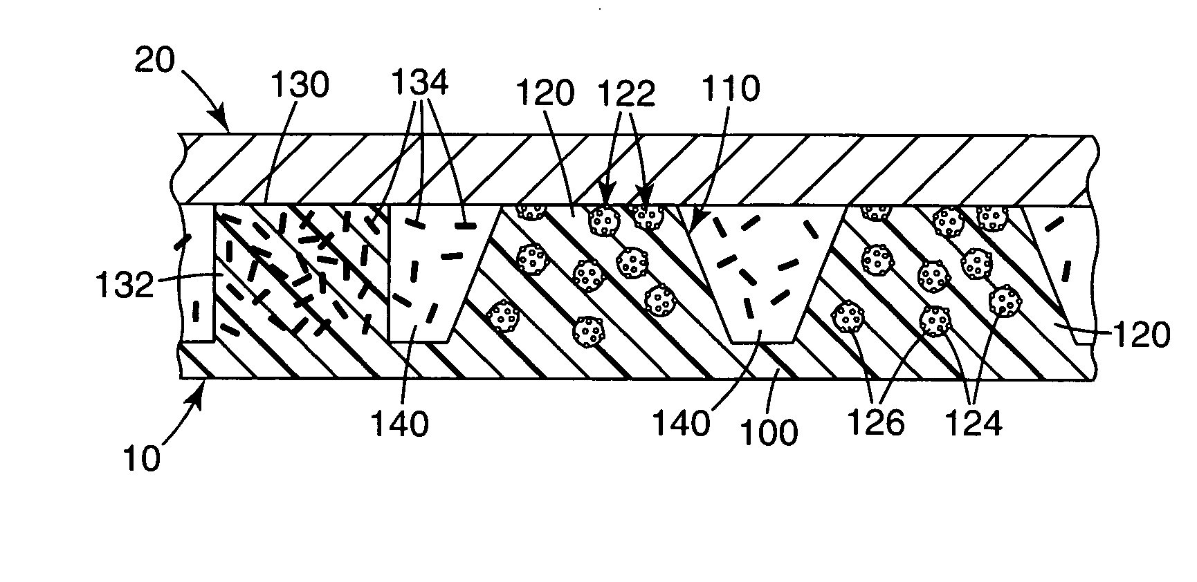
[0060] A fixed abrasive article was prepared by inserting eight 5-cm diameter circular regions of planar conditioning amalgam segments prepared by Method III into a 30.5 cm (12 in.) disk of a fixed abrasive article prepared by Method I. The eight disks were evenly spaced around the perimeter approximately 3.8 cm (1.5 in.) from the edge.

example 2

[0061] A fixed abrasive article was prepared by inserting eight 5-cm diameter circular regions of textured conditioning amalgam segments prepared by Method II into a 30.5 cm (12 in.) disk of a fixed abrasive article prepared by Method I. The eight disks were spaced as in Example 1.

example 3

[0062] A fixed abrasive article was prepared by cutting a 30.5 cm (12 in.) disk from a sheet having alternating stripes of the fixed abrasive article prepared by Method I and the textured conditioning amalgam segment prepared by Method II. The stripes of fixed abrasive article were 5 cm (2 in.) wide and the stripes of textured conditioning amalgam were 2.54 cm (1 in.) wide.


PUM

PropertyMeasurementUnit
particle sizeaaaaaaaaaa

Abstract

Provided is a fixed abrasive article for polishing a workpiece having a hardness comprising (a) a substrate having a first surface and a second surface, (b) a region of abrasive composites distributed on the first surface of the substrate, and (c) a region of conditioning amalgams distributed on the first surface of the substrate. The abrasive composites include a composite binder and abrasive particles of a first hardness, which first hardness is higher than the hardness of the workpiece. The amalgams include an erodible binder and conditioning particles sufficient to condition the composite binder and having a second hardness, which second hardness is less than the hardness of the workpiece and greater than the hardness of the composite binder. Also provided are other abrasive articles, and methods of making them.

Description

TECHNICAL FIELD [0001] This invention relates to a material having a first abrasive suitable for polishing a workpiece, which first abrasive is provided in agglomerates, and conditioning particles suitable for conditioning or dressing agglomerates of the first abrasive, and methods for making these materials. BACKGROUND [0002] Coated abrasive articles typically consist of a layer of abrasive grits adhered to a backing. Three-dimensional, textured, fixed abrasive articles include a plurality of abrasive particles and a binder in a pattern. After use, the abrasive grits become dull and worn, so an additional process is used to expose fresh abrasive. [0003] Slurries containing loose abrasive particles dispersed in a liquid and a polishing pad also have been used for polishing. Lapping is a grinding process that typically involves a slurry of loose abrasive grits, such as aluminum oxide in a liquid, flowed across a rotating lap plate, typically a metal such as cast iron. This provides a...

Claims


Application Information

Patent Timeline
Patent Type & Authority Applications(United States)
IPC IPC(8): B24D11/00
CPCB24B37/245C09K3/1436B24D7/063B24B53/017B24B37/24B24D7/06
Inventor FLETCHER, TIMOTHY D.LUGG, PAUL S.ROMERO, VINCENT D.
Owner 3M INNOVATIVE PROPERTIES CO
Why Eureka
Try Eureka