High frequency synthesizer circuits and methods

Active Publication Date: 2007-02-01
NAVAND TECH CO
View PDF31 Cites 33 Cited by
  • Summary
  • Abstract
  • Description
  • Claims
  • Application Information

AI Technical Summary

Benefits of technology

[0008] Embodiments of the present invention include a frequency synthesizer comprising a first plurality of dividers receiving a first signal having a first frequency and generating a first plurality of divided signals and a frequency combination network including a plurality of mixers, the frequency combin

Problems solved by technology

However, many system components and subsystems may require different frequency signals to operate properly.
While the approach illustrated in FIG. 1 works well in many applications, there are some applications where such an architecture is inadequate.
These frequency changes are sometimes referred to as “channel hopping.” Such an implementation may not wor

Method used


Image

  • High frequency synthesizer circuits and methods
  • High frequency synthesizer circuits and methods
  • High frequency synthesizer circuits and methods

Examples


Example

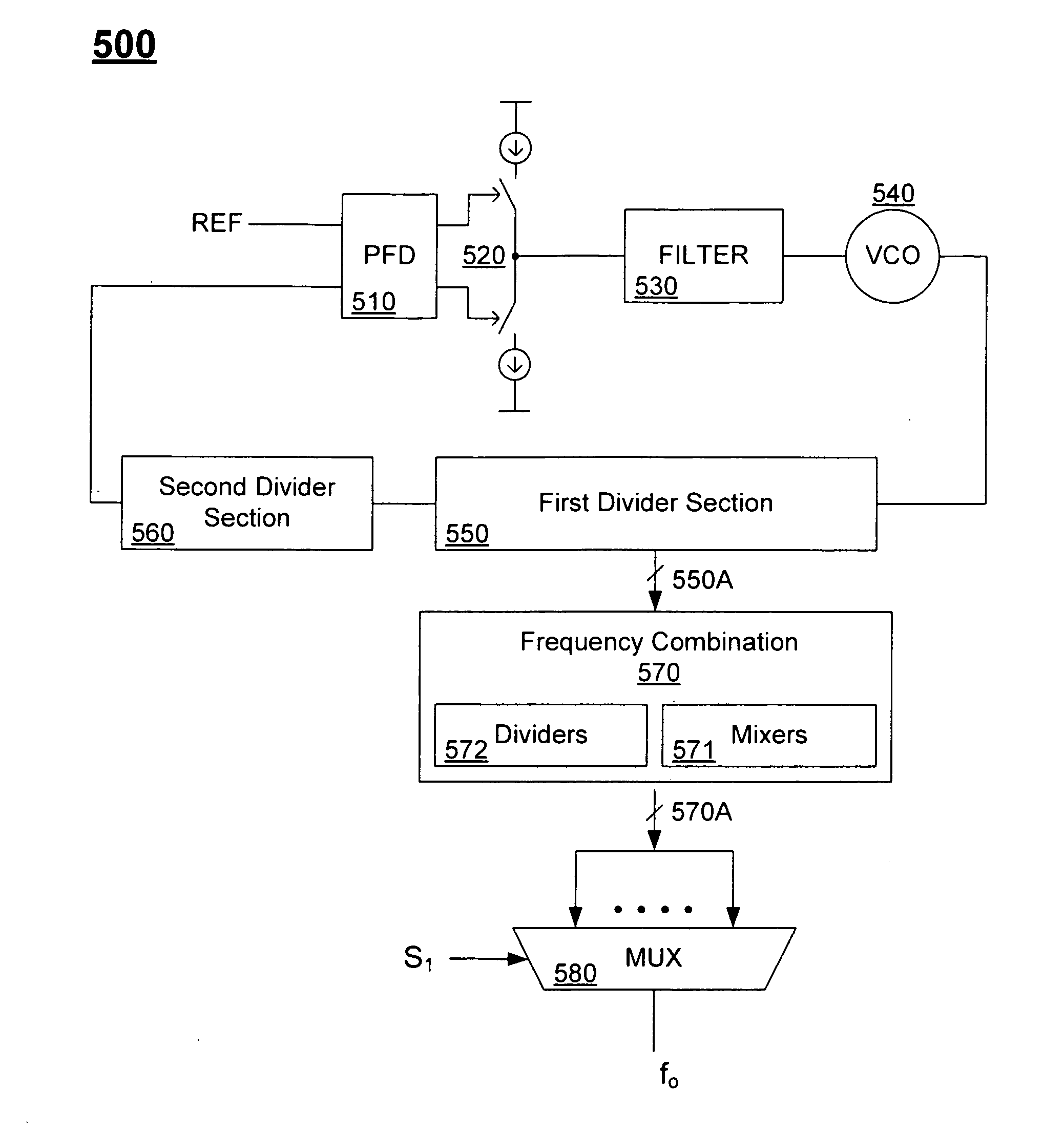
[0029]FIG. 5 illustrates a frequency synthesizer according to one embodiment of the present invention. In this embodiment, the frequencies are derived from the feedback path of a PLL. Thus, frequency synthesizer 500 includes a phase-frequency detector 510, charge pump 520, loop filter 530 and VCO 540. The output of VCO 540 is coupled to a second input of phase detector 510 through the feedback path of the PLL. The feedback path includes two feedback divider sections. A first divider section 550 receives the signals generated by VCO 540 and generates a plurality of divided signals 550A. The first divider section may include series coupled dividers each generating a signal that is some fraction of its input, for example. Such signals are divided versions of the VCO output signal. The second divider section 560 is coupled to the output of first divider section 550 and receives a signal that has a lower frequency than the VCO output signal.

[0030] One feature of the present invention is...


PUM


Abstract

Embodiments of the present invention include a frequency synthesizer comprising a first plurality of dividers receiving a first signal having a first frequency and generating a first plurality of divided signals and a frequency combination network including a plurality of mixers, the frequency combination network receiving one or more of the first plurality of divided signals and generating a plurality of synthesized signals having different frequencies. The frequency combination network may further include additional dividers and multiplexers for more flexibility in synthesizing different frequencies. In one embodiment, the frequency combination network is coupled to dividers in the feedback path of a phase locked loop. The present invention is particularly advantageous for synthesizing frequencies above one (1) gigahertz.

Description

BACKGROUND [0001] The present invention relates to generating signals with specified frequencies, and in particular, to circuits and methods for generating high frequency signals. [0002] Many electronic systems require signals at a variety of different frequencies to perform a variety of different functions. In many situations, a system will include some reference frequency (sometimes referred to as the system frequency). An example of such a reference frequency is a system clock. The reference frequency often provides the foundation timing reference for the system. However, many system components and subsystems may require different frequency signals to operate properly. In many cases, subsystem frequencies may vary drastically from the reference, or may have different tolerances or other unique requirements that the reference frequency cannot meet. Thus, frequency generation, which is sometimes referred to as frequency synthesis, is an important consideration in the design and dev...

Claims


Application Information

Patent Timeline
IPC IPC(8): H04B1/40H04B7/00
CPCH03D7/1441H03L7/0891H03L7/183H03D2200/0043H03D7/1483H03D7/165H03D7/1458
Inventor HEIDARI, MOHAMMAD E.MIZAEI, AHMADDJAFARI, MASOUDCHOI, MIKEBARON, FILIPP A.MEHRNIA, ALIREZABAGHERI, RAHIM
Owner NAVAND TECH CO
Why Eureka
Try Eureka