
Multi-composite disc prosthesis

a multi-composite, disc technology, applied in the field of implantable prosthesis, can solve the problems of deterioration, annulus and facet joints are not capable of withstanding their increased share, and the effect of restoring a more normal distribution of pressur

Active Publication Date: 2007-02-01
NEXT ORTHOSURGICAL INC
View PDF98 Cites 36 Cited by
  • Summary
  • Abstract
  • Description
  • Claims
  • Application Information

AI Technical Summary

Benefits of technology

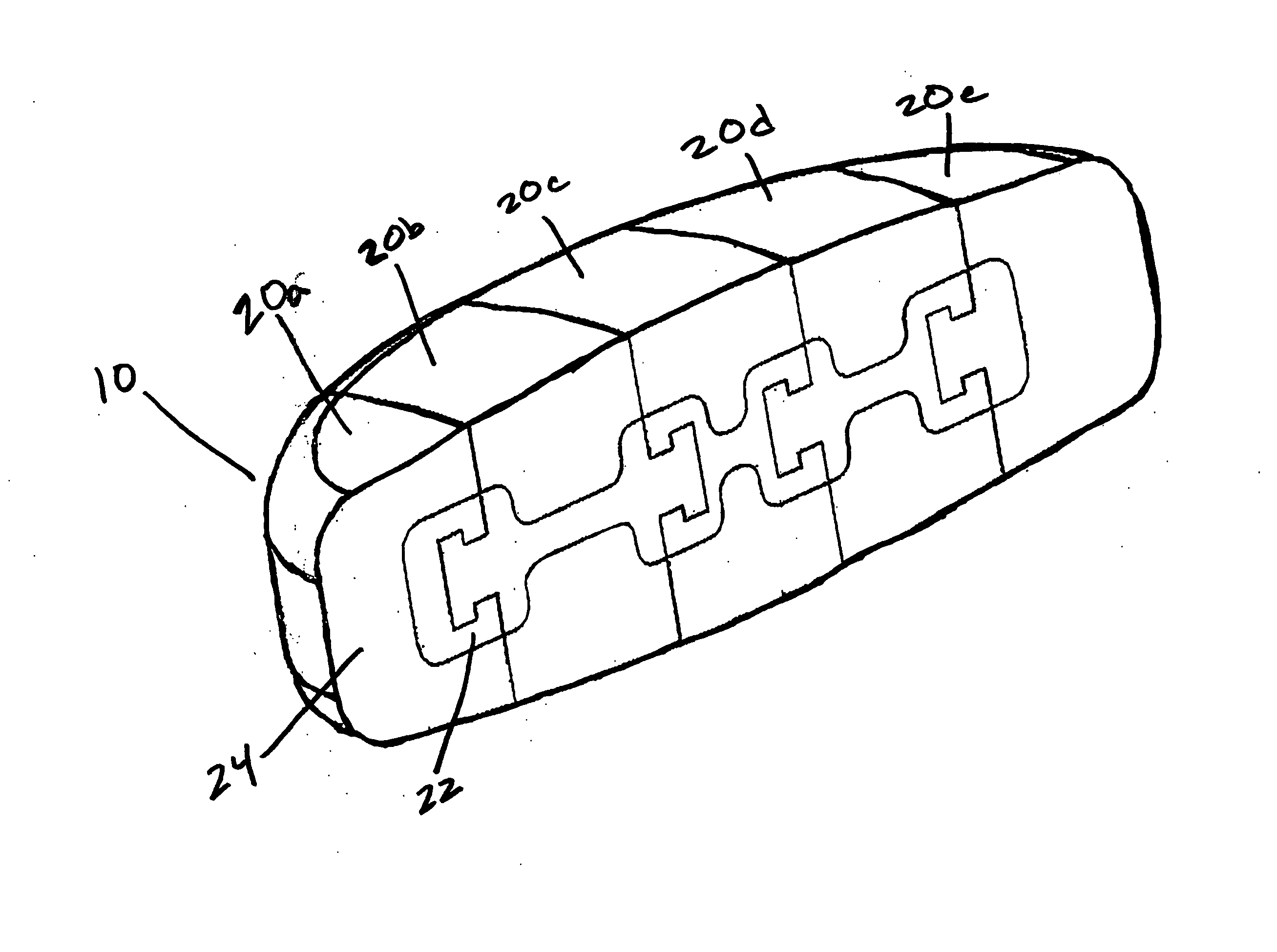
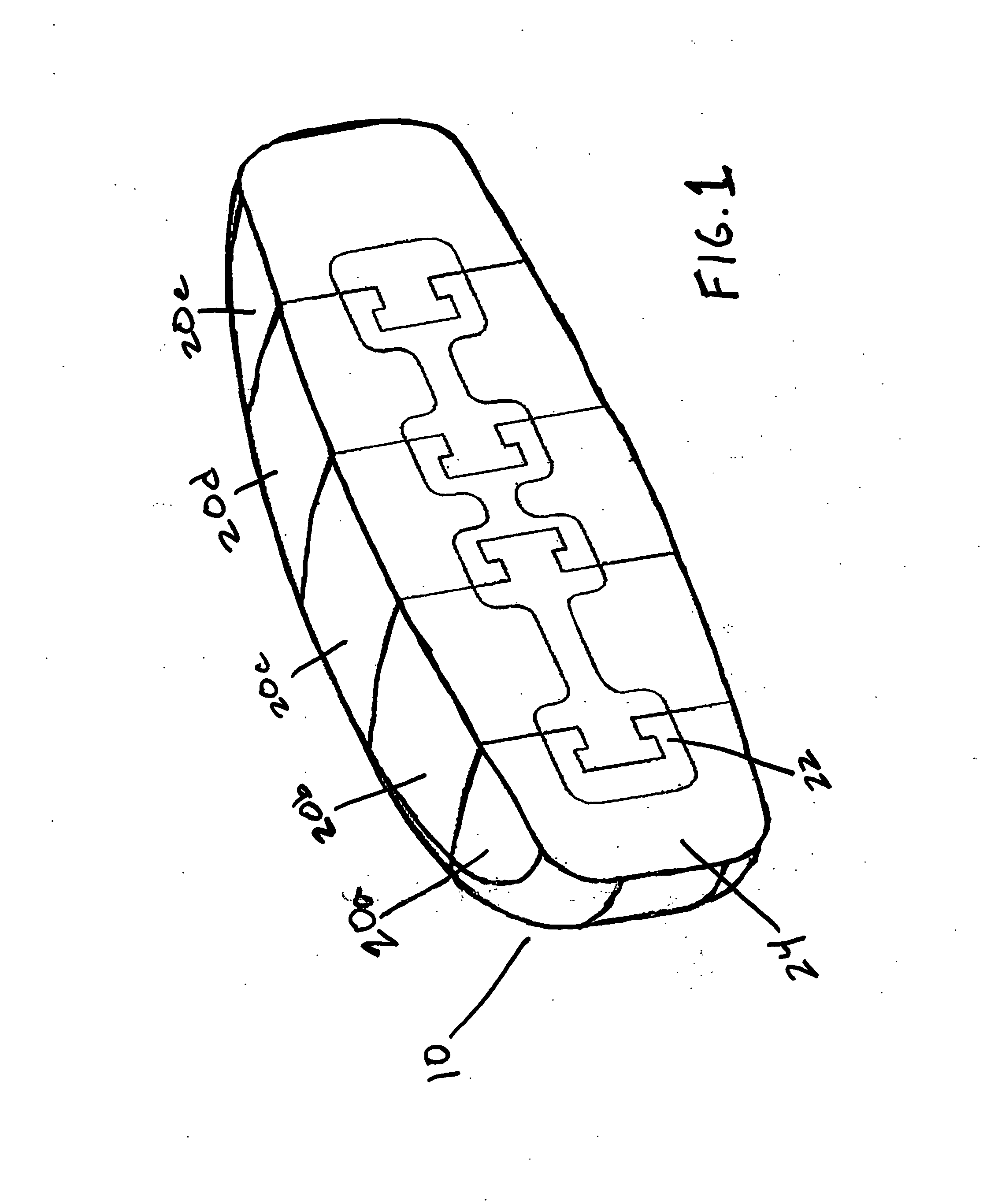
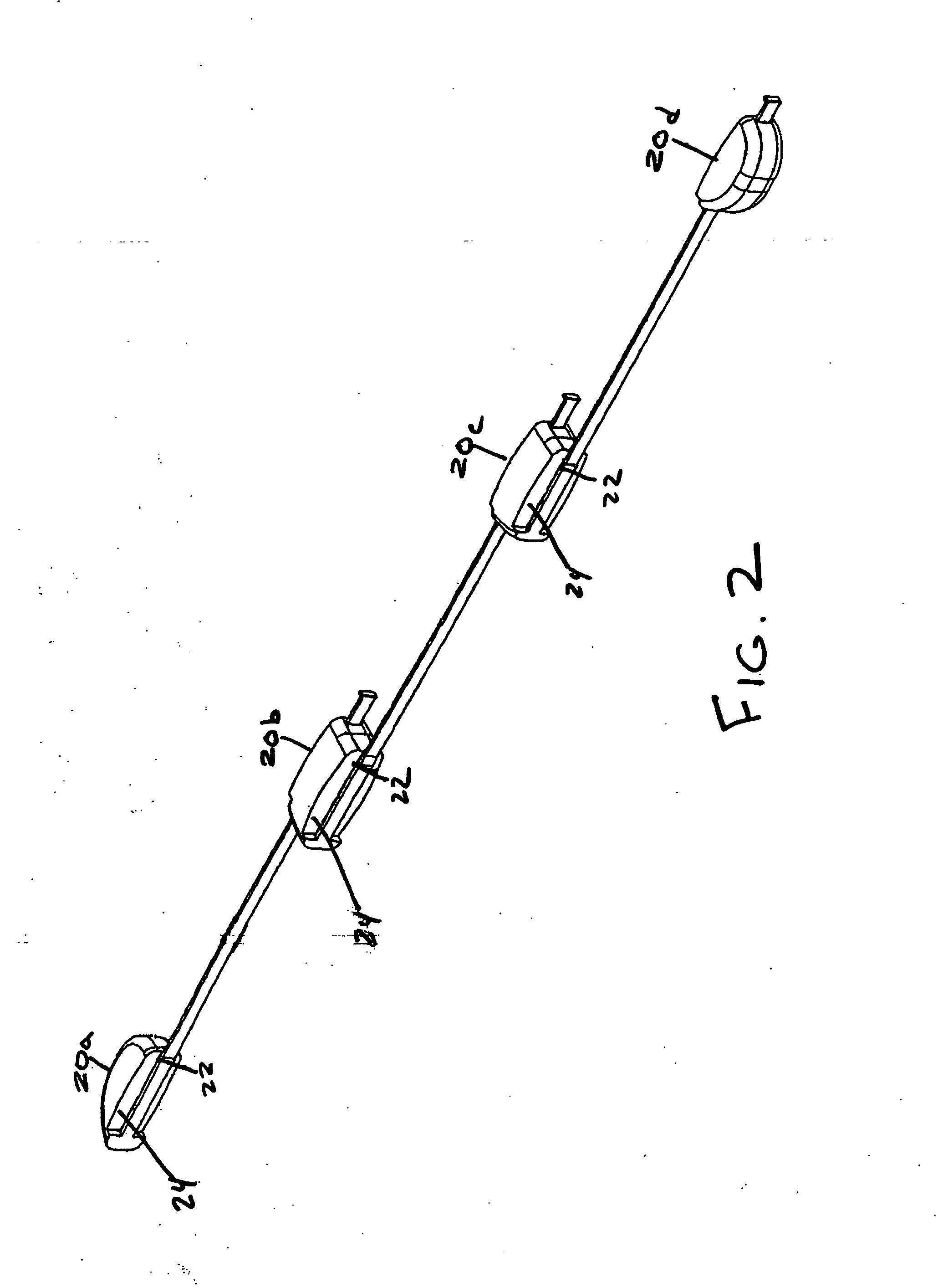
"The present invention is a multi-composite disc prosthesis that can be implanted within the spine to replace the disc nucleus. The prosthesis is made of two biomaterials that are bonded together to form a solid body. The prosthesis can be inserted through a minimally invasive procedure and offers pain relief by restoring a more normal distribution of pressure between the annulus and the nucleus. The prosthesis consists of an outer soft modulus biomaterial and an inner hard modulus biomaterial that may be chemically bonded or connected by a track. The invention can be formed of several interconnected segments that slide along a track."

Problems solved by technology

However, the annulus on its own is not very effective in withstanding compression and shear forces.
The annulus and facet joints are not capable of withstanding their increased share of the applied compression and torsional loads, and as such, they gradually deteriorate.
These breakdown products stimulate sensitive nerve endings in and around the disc, producing low back pain and sometimes, sciatica.
Affected individuals experience muscle spasms, reduced flexibility of the low back, and pain when ordinary movements of the trunk are attempted.
Even in the cases where re-stabilization occurs, the process can take many years and patients often continue to experience disabling pain.
While this treatment is often effective at relieving back pain, all discal motion is lost in the fused spinal motion segment.
The loss of motion in the affected spinal segment necessarily limits the overall spinal mobility of the patient.
Ultimately, the spinal fusion places greater stress on the discs adjacent the fused segment as these segments attempt to compensate for lack of motion in the fused segment, often leading to early degeneration of these adjacent spinal segments.
Total disc replacement is a highly invasive and technically demanding procedure which accesses the disc from an anterior or frontal approach and includes dividing the anterior longitudinal ligament, removing the cartilaginous end plates between the vertebral bone and the disc, large portions of the outer annulus and the complete inner nucleus.
First, because the artificial disc prostheses are relatively large, they require relatively large surgical exposures to accommodate their insertion.
The larger the surgical exposure, the higher the chance of infection, hemorrhage or even morbidity.
Removing a large portion of the annulus reduces the stability of the motion segment, at least until healing occurs around the artificial disc.
Further, because the devices are constructed from rigid materials, they can cause serious damage if they were to displace from the disc space and contact local nerve or vascular tissues.
Another disadvantage is that rigid artificial disc replacements do not reproduce natural disc mechanics.
However, there is usually a trade-off in that the more expansion the hydrogel achieves, the less structural support the end product can provide.
Without the jacket or other form of constraint, the hydrogel is susceptible to displacement because of the slippery nature of the hydrogel.
Unfortunately, the jacket or fabric shell will be subject to long term abrasive wear issues that could result in failure of jacket or shell's ability to constrain the hydrogel and thus the hydrogel may be subject to displacement.
One of the problems with this approach is that the chemical hardening process is exothermic and can generate significant amounts of heat that may cause tissue damage.
In addition, there is a possibility that the balloon may rupture during expansion, causing leakage of material into the disc cavity and surrounding tissues, which may cause undesirable complications.
While seemingly similar to the natural soft-hard combination of the disc nucleus and annulus, these implants still have the same approach and problems as the sandwiched metal and polymer implants.

Method used


Image

  • Multi-composite disc prosthesis
  • Multi-composite disc prosthesis
  • Multi-composite disc prosthesis

Examples


Embodiment Construction

[0025] In contrast to conventional disc or nucleus replacements, the present invention comprises a composite system wherein the outer portion consists of soft modulus material mimicking the natural disc and the inner portion consists of harder modulus material which provides support and stability. Two biocompatible polymers may be chemically bonded to form the composite system of the present invention. Many conventional total disc replacements include upper and lower rigid plates and a non-rigid material disposed therebetween, while other existing nuclear replacements consist of a mass of soft material without a stabilizing hard inner core. The composite system of the present invention offers advantages over the existing devices in that the soft outer portion provides cushioning while not eroding the endplates as may happen with harder materials of other disc nucleus replacements. Further, the soft outer portion is deformable to correspond to the desired modulus in response to norma...


PUM


Abstract

A multi-composite disc prosthesis is adapted to be implanted within the annulus of an evacuated disc nucleus space in a human spine. The disc prosthesis has a generally solid unitary body with a size and a shape adapted to be positioned within the annulus of the evacuated disc nucleus space. The body has an outer portion comprised of a first biomaterial and an inner portion comprised of a second biomaterial. The second biomaterial has a compressive modulus that is harder than a compressive modulus of the first biomaterial and the first and second biomaterials are chemically or physically bonded to form a multi-composite material that forms the solid body.

Description

RELATED APPLICATIONS [0001] The present invention claims priority to U.S. Provisional Patent Application No. 60 / 700,459, entitled “SPINE POLYMER PATENT,” filed Jul. 19, 2005 and to co-pending application Ser. No. 11 / 372,357, filed on Mar. 9, 2006 entitled, “INTERLOCKED MODULAR DISC PROSTHESIS,” each of which in turn claims priority to U.S. Provisional Patent Application No. 60 / 685,332, entitled “SPINE DISC NUCLEUS II,” filed May 24, 2005, U.S. Provisional Patent Application No. 60 / 660,107, entitled “MODULAR DISC PROSTHESIS,” filed Mar. 9, 2005, and also U.S. Provisional Patent Application No. 60 / 700,459, entitled “SPINE POLYMER PATENT,” filed Jul. 19, 2005, the disclosures of all of which are hereby incorporated by reference. The present invention is also related to co-pending application Ser. No. 11 / 372,477, filed on Mar. 9, 2006, entitled, “RAIL-BASED MODULAR DISC NUCLEUS PROSTHESIS,” the disclosure of which is hereby incorporated by reference.FIELD OF THE INVENTION [0002] The pre...

Claims


Application Information

Patent Timeline
Patent Type & Authority Applications(United States)
IPC IPC(8): A61F2/44
CPCA61F2/3094A61F2250/0019A61F2/4455A61F2/4611A61F2002/30014A61F2002/30016A61F2002/30075A61F2002/30166A61F2002/30235A61F2002/30383A61F2002/30387A61F2002/30462A61F2002/3052A61F2002/30561A61F2002/30563A61F2002/30594A61F2002/30604A61F2002/30677A61F2002/30971A61F2002/444A61F2002/4627A61F2210/0061A61F2220/0025A61F2220/0075A61F2230/0028A61F2230/0069A61F2250/0018A61F2/442
Inventor PALM, ERIC E.FELT, JEFFREY C.ZERONI, JENNYSCHAFER, ALBERT
Owner NEXT ORTHOSURGICAL INC
Learn More