Muzzle-loading firearm and easily removable breech plug for use therewith

a breech plug and muzzle-loading technology, which is applied in the field of muzzle-loading firearms, can solve the problems of more difficult and time-consuming loading, more common malfunctions, and greater use skill, and achieve the effects of convenient unloading, convenient removal, and low manufacturing cos

Inactive Publication Date: 2007-02-08
DELEEUW DAVID C
View PDF14 Cites 25 Cited by
  • Summary
  • Abstract
  • Description
  • Claims
  • Application Information

AI Technical Summary

Benefits of technology

[0015] Objects of some embodiments of the present invention are to provide: a muzzle-loader / breech plug design where the breech plug and housing are non-threaded; the breech plug is easily removable; the muzzle-loader and breech plug are relatively inexpensive to manufacture; the muzzle-loader is easily unloaded without firing; the muzzle-loader is easy to clean after firing, and the muzzle-loader cannot be effectively used as, or readily converted to, a breech-loading firearm.

Problems solved by technology

Muzzle-loading rifles have several disadvantages in comparison with breech-loading cartridge rifles.
They are more difficult and time consuming to load, and require greater skill to use.
Malfunctions are more common due to the relatively more complex firing mechanisms required to ignite the powder.
Muzzle-loading rifles are affected by inclement weather, particularly rain and moisture which affects the powder and causes the rifle to misfire.
In addition, many states allow a longer hunting season and special hunting areas for muzzle-loading firearms, due to the greater challenge provided and, consequently, the much smaller number of animals taken.
However, since there is no permanent modification of the firearms themselves in these designs, they would still be useful as, and considered to be, breech-loading firearms.
However, the flame bore extending through these components can become clogged or corroded after repeated use.
This may require that various components be replaced at some expense.
Unfortunately, each of the above-noted muzzle-loader / breech plug designs requires at least a portion of the breech plug to be attached using threaded connections and various “tools” for their insertion and removal.
Such tools are awkward to use and the intricate designs require time-consuming cleaning operations to disassemble, clean powder residue from complex shapes (including threads), and reassemble.
In addition, these complex shapes are expensive to manufacture and these designs are not conducive to unloading by means other than firing the charge.

Method used


Image

  • Muzzle-loading firearm and easily removable breech plug for use therewith
  • Muzzle-loading firearm and easily removable breech plug for use therewith
  • Muzzle-loading firearm and easily removable breech plug for use therewith

Examples


Embodiment Construction

)

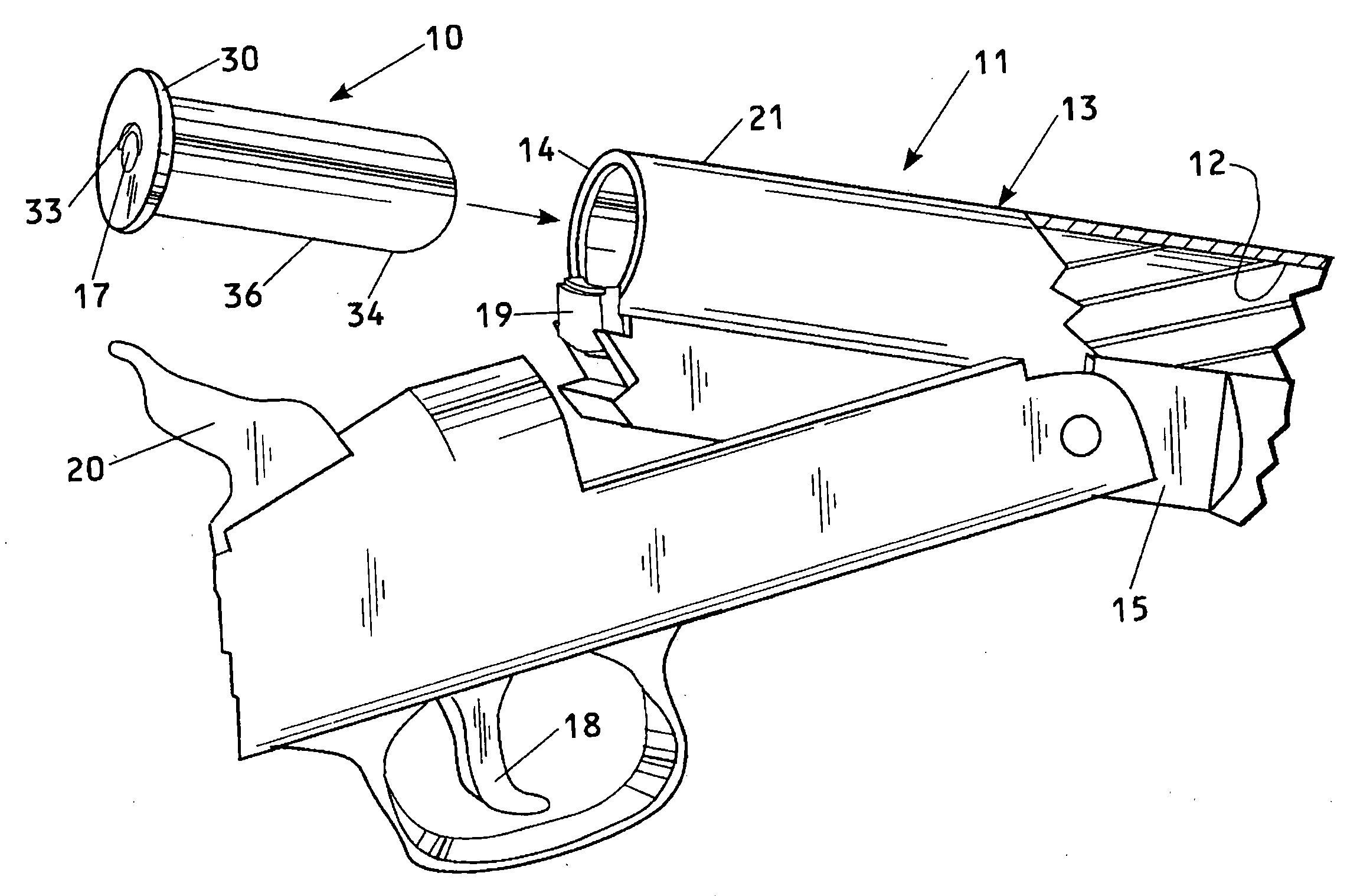
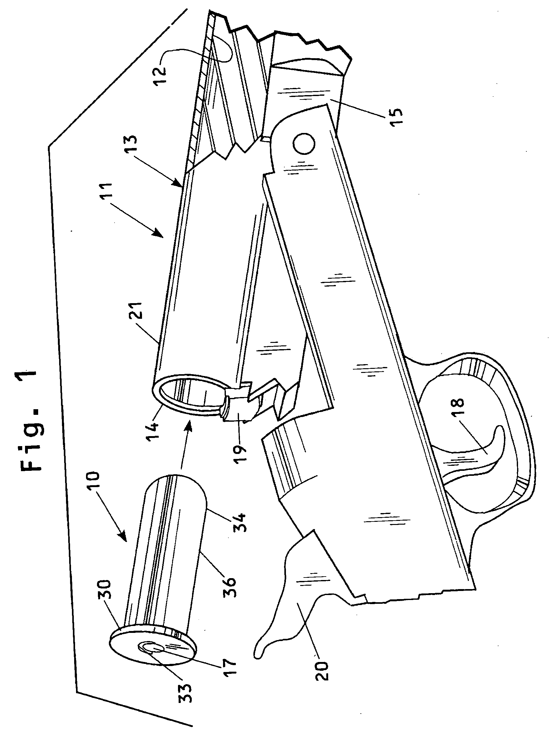
[0038] Referring to FIGS. 1-6, one embodiment of a muzzle-loading firearm or muzzle-loader including a breech plug constructed in accordance with one embodiment of the present invention is schematically indicated. A non-threaded plug 10 is to be inserted slidably into a housing 21 at the breech end 14 of the muzzle-loading firearm, generally indicated at 11 in FIG. 1.

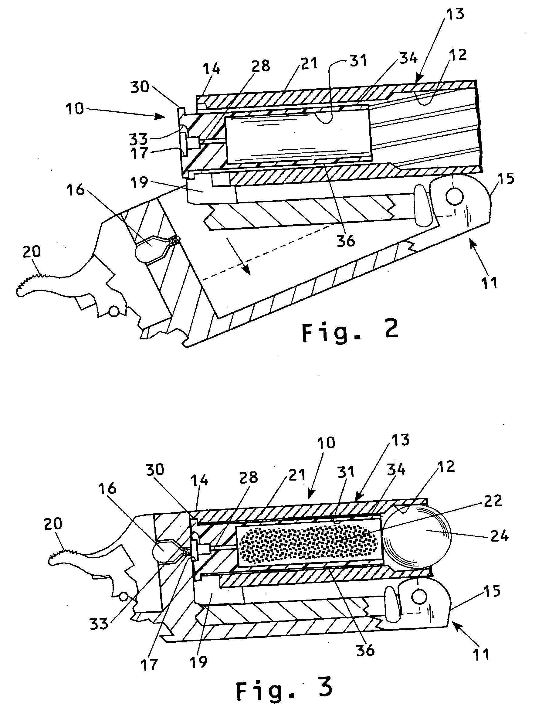
[0039] In the preferred embodiment, the muzzle-loader 11 includes a barrel 13 with the breech end 14 at which is located the cylindrical housing 21. An axial bore 12 of the barrel 13 accepts the non-threaded breech plug 10 wherein the inside diameter of the housing 21 is less than the inside diameter of the bore 12 of the barrel 13. Also, as shown in FIGS. 3 and 4, alignment of a firing pin 16 and a primer holder or chamber 17 (or a hammer 20 and percussion cap holder 17) is along the axis of the bore 12.

[0040] More specifically, referring to FIGS. 1-4, the plug 10 is to be slidably inserted into the housing 21 locat...


PUM


Abstract

A muzzle-loading firearm includes a breech plug for mating, non-threaded engagement with a housing located at the breech end of an axial bore of the firearm barrel. The plug includes a cylindrically-shaped body member having opposite first and second ends and an outer surface between the ends and configured so that when the plug is positioned within the housing, the outer surface is spaced close to the inside surface of the housing to facilitate insertion and removal of the plug from the housing. The body member is formed with a primer chamber for receiving and retaining a primer or a percussion cap at the first end, and a passageway for fluidly communicating the primer chamber with a powder charge at the second end. The body member may have a powder chamber for receiving and retaining at least part of a powder charge at the second end when the firearm is loaded. The material and dimensions of the body member may be such that the body member deforms radially outwardly so that the outer surface of the body member and the inside surface of the housing form an essentially gas-tight seal during firing. The powder chamber contains much of the powder residue generated by the firing. In order to insure that the muzzle-loader cannot be readily used as, or converted to, a breech-loading firearm, different muzzle-loader/breech plug design features are presented. With one design feature, the maximum cross-sectional inner dimension of the housing is less than the diameter of the bore of the barrel. With another design feature, alignment of the firing pin and primer chamber (or hammer and percussion cap holder) is along an axis not centered with the axial bore of the barrel. The cross-sectional shape of the housing and breech plug may be non-cylindrical. For example, the cross-sectional shape can be oblong, essentially triangular, etc. Thus, conventional, breech-loading ammunition will not be effectively usable in the muzzle-loading firearm.

Description

BACKGROUND OF THE INVENTION [0001] 1. Field of the Invention [0002] The invention relates to muzzle-loading firearms and, in particular, to muzzle-loading firearms and non-threaded, easily removable breech plugs for use with such firearms. [0003] 2. Background Art [0004] Modern breech-loading firearms, such as rifles, include a barrel having an axial bore, a stock to support the barrel, and a receiver at the breech end of the barrel. The receiver is comprised of a housing which includes a chamber for insertion of a cartridge into the breech of the barrel, a means for firmly securing the cartridge in the breech of the barrel in a sealed and locked position, a firing pin to discharge the cartridge primer, a trigger to move the firing pin into engagement with the cartridge primer, and an ejector to remove the cartridge after firing. For effective ballistics and accuracy, a close tolerance is required between the outside diameter of a bullet and the bore (inside diameter) of the barrel....

Claims


Application Information

Patent Timeline
Patent Type & Authority Applications(United States)
IPC IPC(8): F41C7/00
CPCF41A3/58F41A3/74F42B5/38F41C9/08F41A21/12
Inventor DELEEUW, DAVID C.
Owner DELEEUW DAVID C
Why Eureka
Try Eureka