Heat transfer apparatus and systems including the apparatus

a technology of heat transfer apparatus and system, applied in the direction of mechanical apparatus, light and heating apparatus, machines/engines, etc., can solve the problems of high heat transfer rate, inability to use additives in many applications, and significant thermal resistance between the surface and the vapor, etc., to promote and stabilize dropwise condensation

Inactive Publication Date: 2007-02-08
GENERAL ELECTRIC CO
View PDF33 Cites 71 Cited by
  • Summary
  • Abstract
  • Description
  • Claims
  • Application Information

AI Technical Summary

Benefits of technology

[0006] Therefore, advances in technologies that promote and stabilize dropwise condensation would be most welcome in the art, par

Problems solved by technology

This so-called “dropwise” condensation results in considerably higher heat transfer rates than filmwise condensation, but dropwise condensation is generally an unstable condition that often becomes replaced by filmwise condensation over time.
These approaches have drawbacks in t

Method used


Image

  • Heat transfer apparatus and systems including the apparatus
  • Heat transfer apparatus and systems including the apparatus
  • Heat transfer apparatus and systems including the apparatus

Examples


example 1

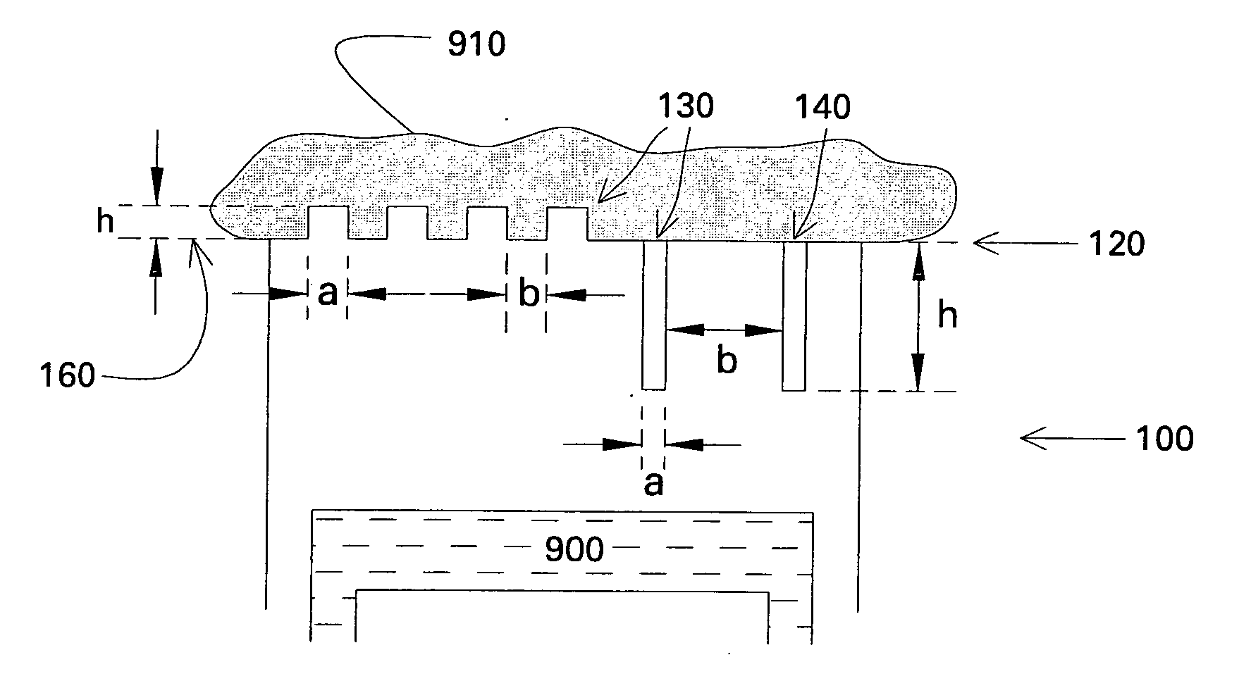
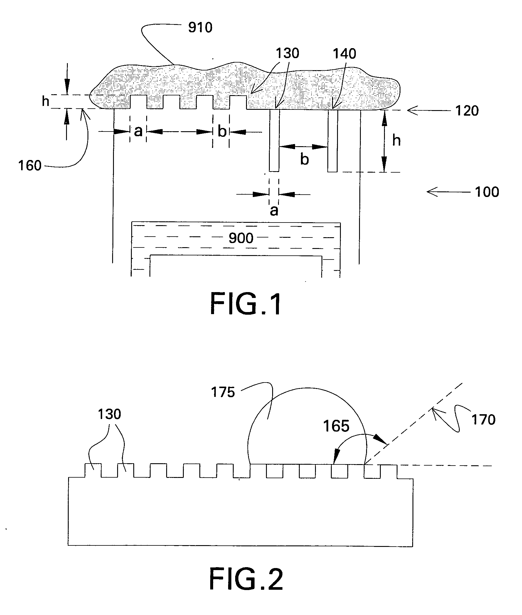
[0060] An apparatus for heat transfer is designed. A maximum allowable drop diameter of up to 3 mm prior to roll-off is determined to be allowable to ensure proper levels of heat transfer. An aluminum tube is to be used as a heat transfer surface, and the surface of the tube that will contact the vapor to be condensed is anodized, using a process known in the art, to provide a layer of anodized aluminum oxide (AAO) of 100 micrometer thickness (h). The anodization process selected to perform this work can be manipulated to provide columnar pores having a median pore diameter (a) of about 10 micrometers with a median edge-to-edge spacing (b) of about 30 micrometers. Thus h / a is about 10 and b / a is about 3. Referring to FIG. 5, the selected process will provide a surface configured to effect roll-off at the desired maximum size for both Wenzel-state and Cassie-state drops. The AAO surface is treated with a very thin layer of fluorosilane, using a vapor deposition method known to the ar...

example 2

[0061] An experimental test apparatus was designed to measure heat transfer associated with condensation of steam. The test setup consisted of a steam generator, a condensing chamber, and a chill block, one end of which is exposed to the steam and the other end to cooler circulating water. The test sample was mounted onto the chill block so that steam condensed onto the surface of the sample. Heat transfer and associated heat transfer coefficients are determined by measuring the temperatures along the length of the block, the surface of the sample, and the temperature of the steam.

[0062] Silicon wafers (4″ diameter) with different surface properties were tested in the above apparatus. Sample A was a regular silicon wafer with water contact angle of about 43 degrees (hydrophilic), and served as a baseline. Sample B was coated with tridecafluoro-1,1,2,2-tetrahydrooctyl-trichlorosilane (fluorosilane) via vapor deposition, to increase its water contact angle to 110 degrees (hydrophobic...

example 3

[0063] A pipe composed of 6061 aluminum with a diameter of about one inch was first polished with fine sandpaper and then coated with anodized aluminum oxide (AAO) via an anodization process. The surface consisted of pores that were on average 90 nm in diameter, 500 nm in depth and a typical edge-to-edge spacing of about 10 nm. This specimen was then coated with fluorosilane via vapor deposition as in Example 1. When the surface was exposed to steam, stable dropwise mode of condensation was observed, with droplets being shed from the surface by rolling off.


PUM

PropertyMeasurementUnit
Lengthaaaaaaaaaa
Angleaaaaaaaaaa
Diameteraaaaaaaaaa

Abstract

An apparatus for the transfer of heat is presented. The apparatus comprises a textured heat transfer surface disposed to promote condensation of a vapor medium to a liquid condensate, the surface comprising a plurality of surface texture features disposed on the heat transfer surface. The plurality of features has a median size, a median spacing, and a median height displacement such that the force exerted by the surface to pin a drop of condensate to the surface is equal to or less than an external force acting to remove the drop from the surface. Also included are heat pumps, systems for power generation, and distillation systems comprising the apparatus.

Description

CROSS REFERENCE TO RELATED APPLICATIONS [0001] This application claims priority to U.S. Provisional Patent Application Ser. No. 60 / 705,239, filed Aug. 3, 2005.BACKGROUND [0002] This invention relates to devices for efficient heat transfer. More particularly, this invention relates to the use of heat transfer surfaces having low surface energy to promote stable dropwise condensation, and devices incorporating these surfaces. [0003] Condensation of a liquid phase from a vapor phase generally occurs when the vapor comes into contact with a surface having a temperature below the saturation temperature of the vapor, as commonly occurs in condenser devices used in power generation and refrigeration systems. The latent heat of vaporization is released during the condensation process, and this heat is transferred to the surface. [0004] Two alternate mechanisms may govern a condensation process. In most cases, the condensing liquid (“condensate”) forms a film covering the entire surface; thi...

Claims


Application Information

Patent Timeline
IPC IPC(8): F02C7/08F28F13/18
CPCF28F2245/04F28F13/187
Inventor VARANASI, KRIPA KIRANBHATE, NITINO'NEIL, GREGORY ALLENGANTI, SURYAPRAKASHSTEIN, JUDITHDENG, TAOTURNQUIST, NORMAN ARNOLDBRUN, MILIVOJ KONSTANTINGHASRIPOOR, FARSHADKRISHNAN, KASIRAMANKEIMEL, CHRISTOPHER FRED
Owner GENERAL ELECTRIC CO
Why Eureka
Try Eureka