Loop type thermo siphon, stirling cooling chamber, and cooling apparatus

a technology of thermosyphon and cooling chamber, which is applied in the direction of domestic cooling apparatus, indirect heat exchangers, lighting and heating apparatus, etc., can solve the problems of improving heat radiation performance limit, and achieve the effect of reliably circulating coolant and high performan

Inactive Publication Date: 2007-02-08
SHARP KK
View PDF8 Cites 48 Cited by
  • Summary
  • Abstract
  • Description
  • Claims
  • Application Information

AI Technical Summary

Benefits of technology

[0050] The loop thermosyphon in the first to fourth aspects of the present invention can be prevented from defective operation regardless of disposition. Furthermore the Stirling refrigerator of the present invention can exhibit high performance regardless of how the casing is disposed.
[0051] Furthermore in the cooling apparatus in the first and second aspects of the present invention as a Stirling refrigerating machine is driven a heated portion generates heat, which is transferred and externally radiated by a thermosyphon utilized in a heat transfer cycle associated with the heated portion and having a condensate coolant pipe passing the coolant's condensate na

Problems solved by technology

It thus has its limit in improv

Method used


Image

  • Loop type thermo siphon, stirling cooling chamber, and cooling apparatus
  • Loop type thermo siphon, stirling cooling chamber, and cooling apparatus
  • Loop type thermo siphon, stirling cooling chamber, and cooling apparatus

Examples


first embodiment

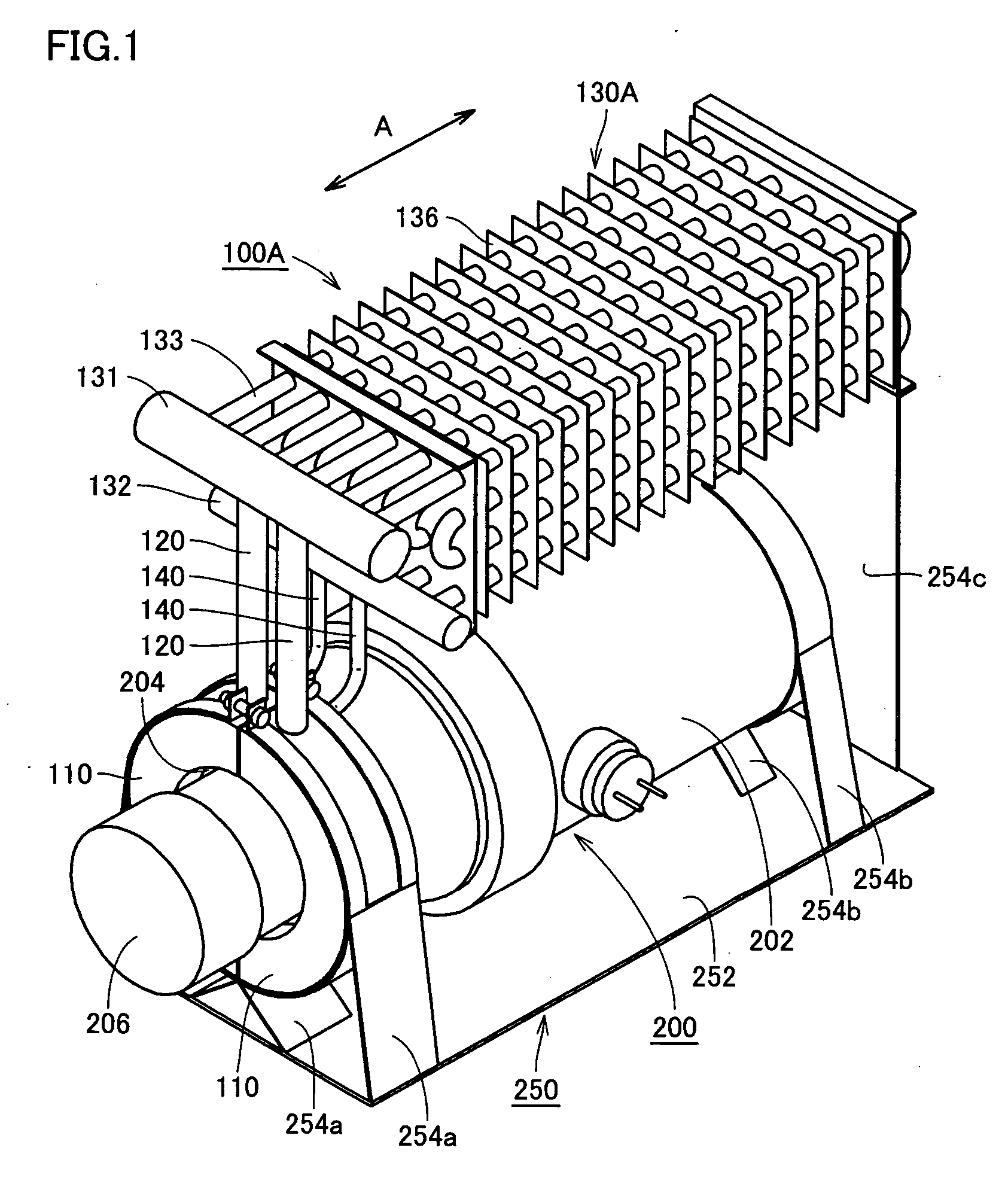
[0073] Initially reference will be made to FIG. 1 to describe a loop thermosyphon in the present embodiment and a structure of a Stirling refrigerating machine installed with the loop thermosyphon attached thereto.

[0074] As shown in the figure, a Stirling refrigerating machine 200 is placed on a supporting platform 250 and supported by supports 254a, 254b provided on platform 250 at a bottom plate 252. Furthermore, a loop thermosyphon 100A is also placed on platform 250 and supported thereon by support 254a, 254c provided at a bottom plate 252. Stirling refrigerating machine 200 and loop thermosyphon 100A supported by platform 250 are disposed in a casing of prescribed equipment (e.g., a refrigerator). Note that platform 250 has bottom plate 252 parallel to a bottom surface of the casing of the equipment.

[0075] Stirling refrigerating machine 200 is structured and operates, as described hereinafter.

[0076] As shown in FIG. 1, Stirling refrigerating machine 200 includes a pressure c...

second embodiment

[0105] The present embodiment provides a loop thermosyphon 100B also utilized as a heat transfer system associated with a heated portion of a Stirling refrigerating machine, similarly as described in the first embodiment. Accordingly, the components similar to those of the first embodiment are shown in the figures with identical reference characters.

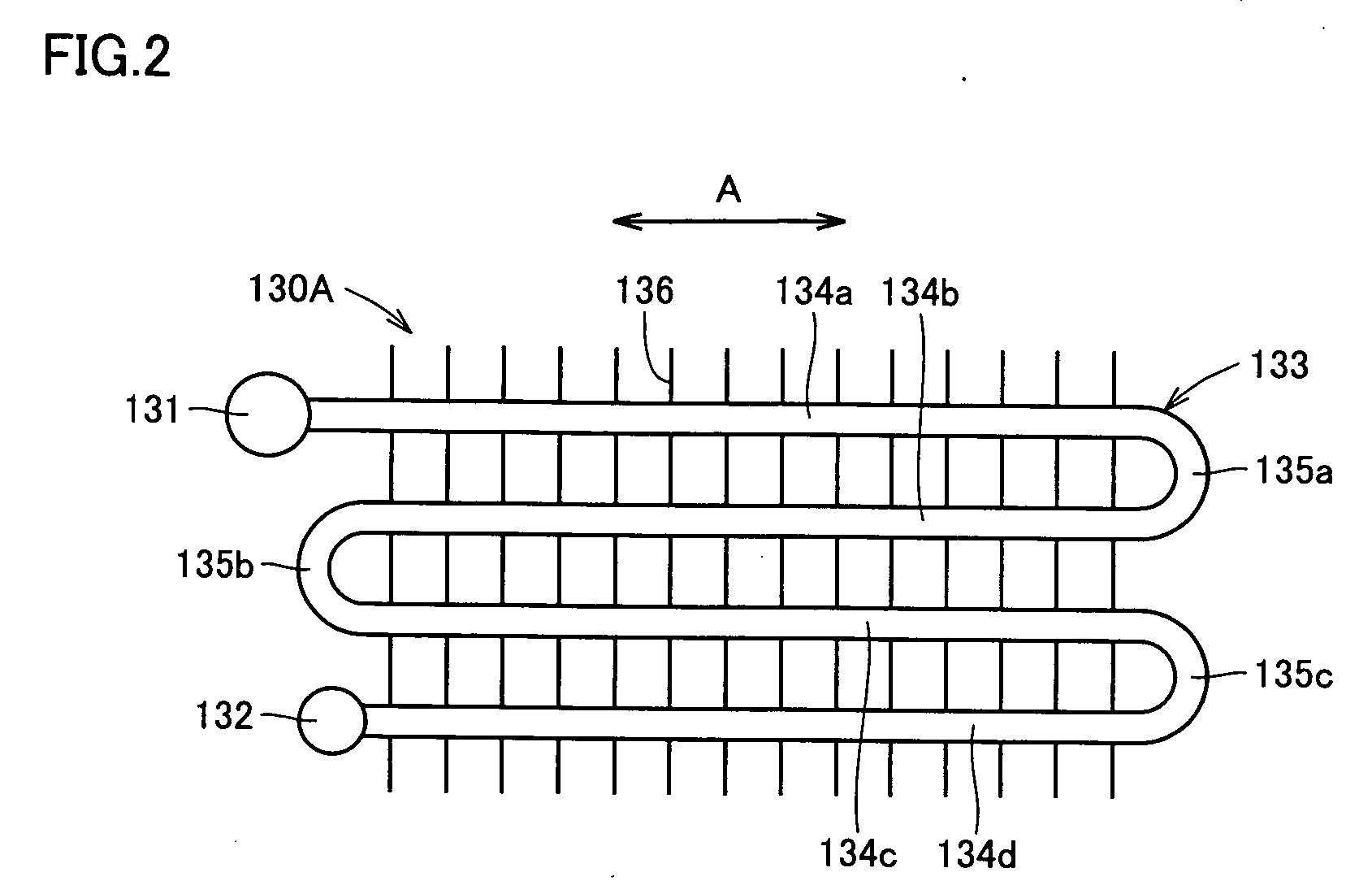
[0106] As shown in FIGS. 6A and 6B, the present embodiment provides loop thermosyphon 100B with a condenser 130B similar to condenser 130A of loop thermosyphon 100A described in the first embodiment. More specifically, condenser 130B is unitized as an assembly formed of header pipe 131 associated with a feed pipe, header pipe 132 associated with a return pipe, the plurality of aligned pipes 133 connecting header pipes 131 and 132 together, and a radiating fin 136 provided in contact with aligned pipes 133.

[0107] Aligned pipe 133 has a linear portion extending in a first direction (indicated in the figure by an arrow A), and header pipe...

third embodiment

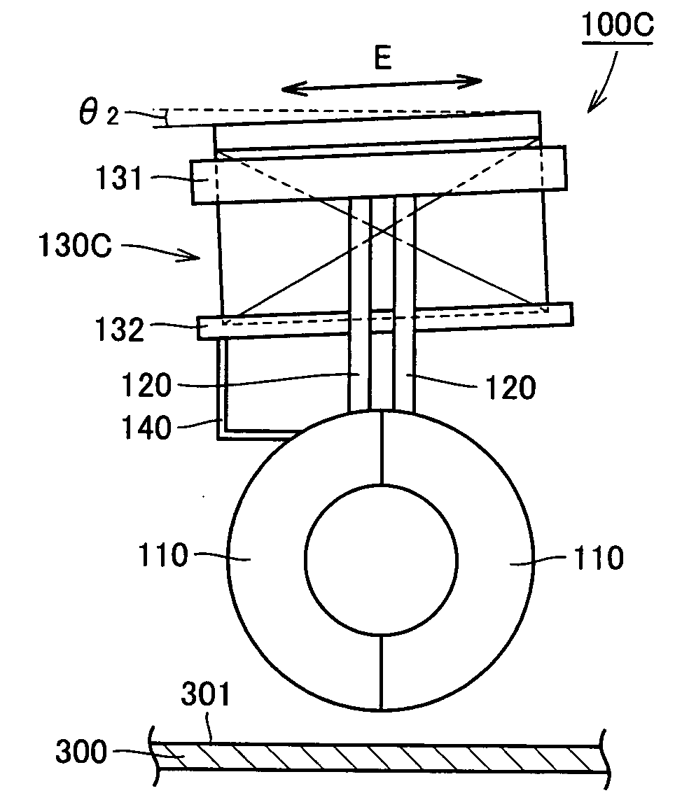
[0115] The present embodiment provides a loop thermosyphon 100C also utilized as a heat transfer system associated with a heated portion of a Stirling refrigerating machine, similarly as described in the first or second embodiment. Accordingly, the components similar to those of the first or second embodiment are shown in the figures with identical reference characters.

[0116] As shown in FIGS. 7A and 7B, the present embodiment provides loop thermosyphon 100C with a condenser 130C similar to condensers 130A and 130B of loop thermosyphons 100A and 1001B described in the first and second embodiments. More specifically, condenser 130C is unitized as an assembly formed of header pipe 131 associated with a feed pipe, header pipe 132 associated with a return pipe, the plurality of aligned pipes 133 connecting header pipes 131 and 132 together, and radiating fin 136 provided in contact with aligned pipes 133.

[0117] In the present embodiment condenser 130C is arranged to entirely incline b...


PUM


Abstract

A loop thermosyphon includes a closed circuit configured of an evaporator, a condenser, a feed pope and a return pope, and the evaporator is an assembly including a header pipe associated with the feed pope, a header pipe associated with the return pipe, and a plurality of aligned pipes. Each of the aligned popes is a serpentine tube defined by a linear portion forming a plurality of stages in vertically parallel layers, and a curved portion connecting such linear portions together. The condenser is entirely inclined relative to a bottom surface of a casing mounting the loop thermosyphon such that the serpentine tube's linear portions have a bottommost linear portion inclined in a direction allowing the bottommost linear portion to be closer to the bottom surface of the casing as the bottommost linear portion approaches the header pipe associated with the return pipe.

Description

TECHNICAL FIELD [0001] The present invention relates generally to loop thermosyphons, Stirling refrigerators having the loop thermosyphon mounted, and cooling apparatuses equipped with a Stirling refrigerating machine. BACKGROUND ART [0002] Conventionally, heat radiation systems employing heat sinks, heat pipes, thermosyphons and the like have been known as heat radiation systems radiating heat generated from heat sources. For a heat radiation system with a heat sink attached to a heat source, the heat sink has a significant distribution in temperature. As such, the remoter it is from the heat source, the less it contributes to heat radiation. It thus has its limit in improving heat radiation performance. In contrast, heat radiation systems employing a heat pipe, a thermosyphon or the like employ a working fluid to transfer heat generated at a heat source. As such, they have a significantly higher ability to transfer heat than a heat sink and can thus maintain high heat radiation pe...

Claims


Application Information

Patent Timeline
IPC IPC(8): F25B9/00F28D15/00F25B9/14F25B23/00F25B25/00F25D11/00F28D15/02
CPCF25B9/14F25B23/006F25B25/00F28D2015/0216F25D11/00F25D2317/0682F28D15/0266F25B2500/01F28D1/047F28D15/02
Inventor CHEN, WEI
Owner SHARP KK
Why Eureka
Try Eureka