EGR cooler system

Inactive Publication Date: 2007-02-08
TOYOTA JIDOSHA KK
View PDF1 Cites 32 Cited by
  • Summary
  • Abstract
  • Description
  • Claims
  • Application Information

AI Technical Summary

Benefits of technology

[0010] With the structure according to the aspect of the invention described above, the coolant to be supplied to the EGR cooler is cooled by the EGR cooler cooling device. The EGR cooler cooling device is provided in the coolant path that is separate from the path provided with the engine cooling system which cools the coolant to be supplied to the heated portion of the internal combustion engine. The flow control valve regulates the amount of coolant flowing into the bypass passage based on the temperature of the coolant flowing through the coolant path provided with the EGR cooler cooling device. The coolant may bypass the EGR cooler cooling device or the water-cooled EGR cooler through the bypass passage. As a result, the

Problems solved by technology

If such high-temperature coolant is supplied to the EGR cooler, the exhaust gas cannot be sufficiently cooled.
If such excessively cooled coolant is supplied to the EGR cooler, the exhaust gas is also exc

Method used


Image

  • EGR cooler system
  • EGR cooler system

Examples


Example

[0013] In the following description, the invention will be described in more detail in terms of an example embodiment.

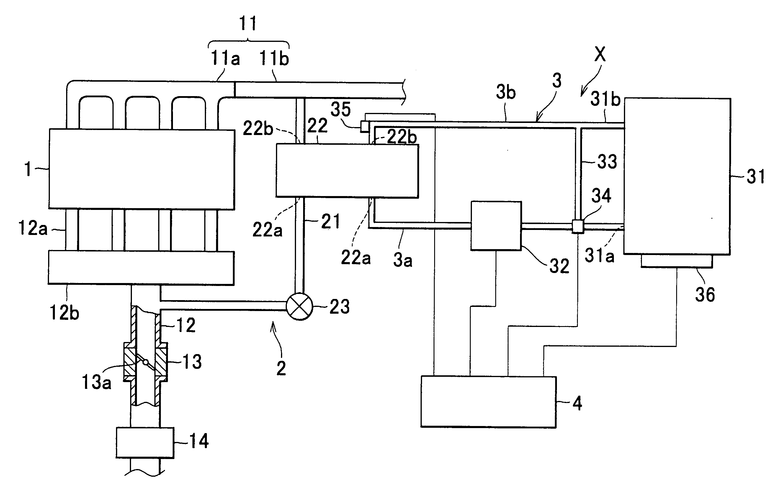
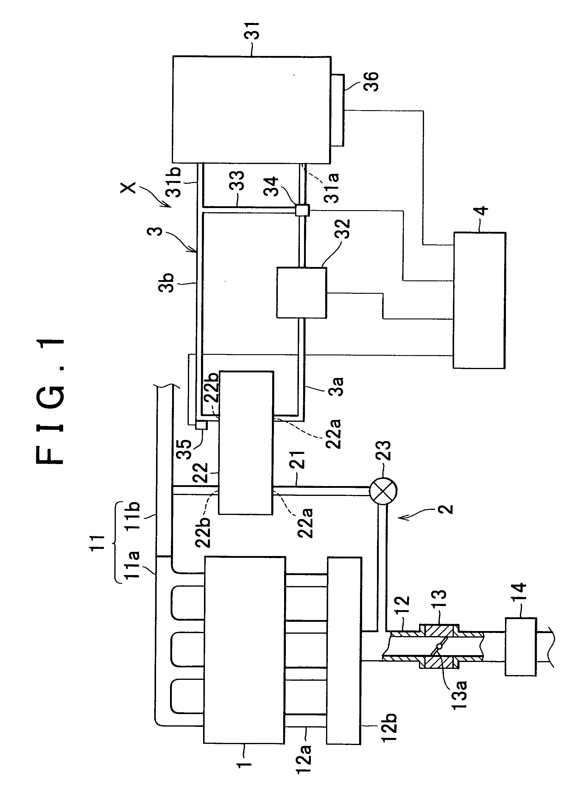
[0014]FIG. 1 shows the schematic view of the structure of an EGR cooler system according to an embodiment of the invention, which is provided for an exhaust gas recirculation system. As shown in FIG. 1, an exhaust manifold 11a is connected to the exhaust ports of an in-line four-cylinder internal combustion engine 1. An exhaust pipe 11b is connected to the exhaust manifold 11a. The exhaust manifold 11a and the exhaust pipe 11b form an exhaust passage 11. An intake pipe 12a is connected to the internal combustion engine 1. A surge tank 12b is formed integrally with an intake passage 12. A throttle body 13 housing a throttle valve 13a, and an air-cleaner 14, which is provided upstream of the throttle body 13, are provided in the intake passage 12. An exhaust gas recirculation system 2 is provided between the exhaust passage 11 and the intake passage 12. The exhaust ga...


PUM


Abstract

An EGR cooler system according to the invention includes an EGR cooler cooling device the is provided in a coolant path which is separate from the path provided with an engine cooling system which cools coolant. The EGR cooler cooling devices cools the coolant to be supplied to a water-cooled EGR cooler. The EGR cooler system also includes a water pump that circulates the coolant within the coolant path; a bypass passage through which the coolant may bypass the EGR cooler cooling device or the water-coolant EGR cooler; and a flow control valve that regulates the amount of coolant flowing into the bypass passage based on the temperature of the coolant flowing through the coolant path.

Description

INCORPORATION BY REFERENCE [0001] The disclosure of Japanese Patent Application No. 2005-223766 filed on Aug. 2, 2005 including the specification, drawings and abstract is incorporated herein by reference in its entirety. BACKGROUND OF THE INVENTION [0002] 1. Field of the Invention [0003] The invention relates to an EGR cooler system for an exhaust gas recirculation system. The exhaust gas recirculation system sends part of the exhaust gas from an exhaust passage of an internal combustion engine back to an intake passage of the internal combustion engine. The EGR cooler system cools the exhaust gas to be sent back to the intake passage using a water-cooled EGR cooler. [0004] 2. Description of the Related Art [0005] Usually, generation of NOx is suppressed as follows; part of the exhaust gas is extracted and cooled by a water-cooled EGR (Exhaust Gas Recirculation) cooler, and the cooled exhaust gas is sent back to an intake passage of the internal combustion engine to reduce the comb...

Claims


Application Information

Patent Timeline
IPC IPC(8): F02M25/07F02B47/08F28F27/02F28F9/02
CPCF02M25/0728Y02T10/121F02M25/0754F02M25/0731F02M26/25F02M26/28F02M26/47
Inventor NIGORO, TAKUYAYOKOI, TATSUHISAIEMURA, AKIYUKIIDE, TETSUOSASAKI, SEIJIKUSUNOKI, RYOUHEIYAMAMOTO, TOSHIO
Owner TOYOTA JIDOSHA KK
Why Eureka
Try Eureka