
Machine for transferring power and producing electricity in a jet engine

a jet engine and power transfer technology, applied in the direction of machines/engines, efficient propulsion technologies, electric generator control, etc., can solve the problems of reducing the efficiency of a jet engine, the inability to adapt to the variable air flow of the rotating compressor or the turbine stage, and the addition of various shafts and bearings to the weight of the jet engine, so as to reduce the total weight and system complexity, the effect of eliminating the sha

Inactive Publication Date: 2007-02-08
RANDALL EDWARD RIGOR
View PDF5 Cites 12 Cited by
  • Summary
  • Abstract
  • Description
  • Claims
  • Application Information

AI Technical Summary

Benefits of technology

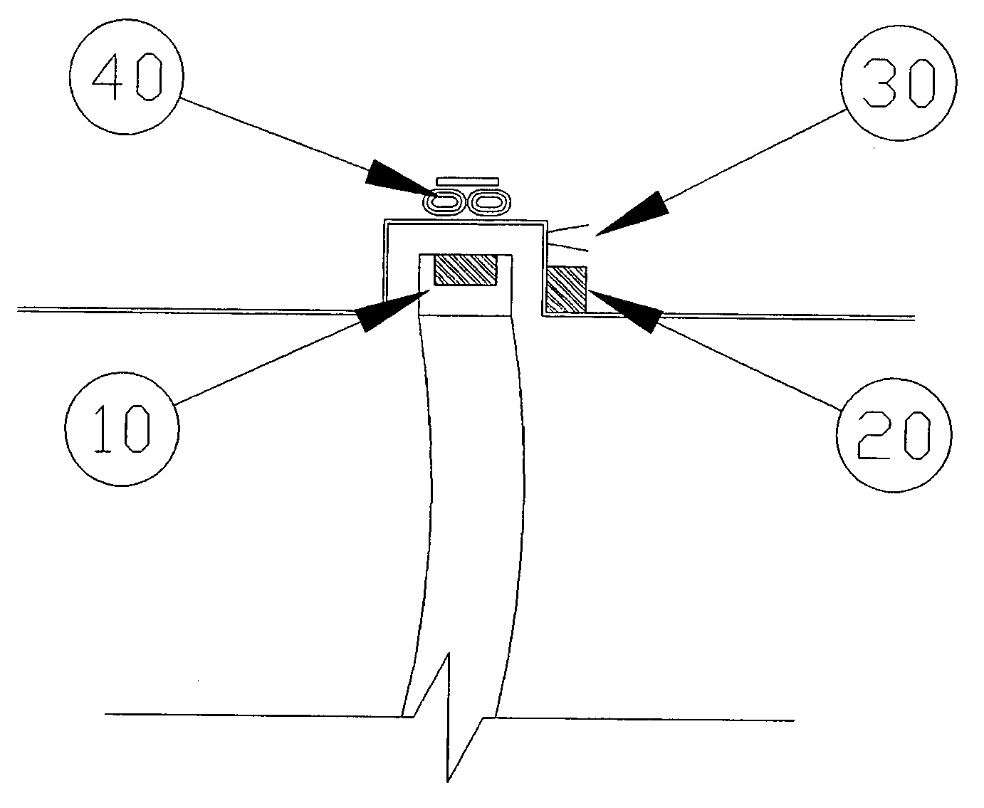
"The invention is a machine that connects the turbine and compressor in a jet engine using electricity. It eliminates the shaft, reducing weight by about ⅓. It also eliminates shaft-driven generators, reducing complexity. It increases engine output for auxiliary systems and creates a modular system where electrical output can be increased or decreased by adding or removing turbine stages. It enables individual control of each compressor stage, increasing efficiency. The invention includes a ring containing embedded high energy magnets, a set of coils for each rotating stage, a power transfer and distribution system, a control system, a storage system, magnetic bearings for each rotating stage, and a cooling system for the first couple turbine stages to keep the magnets from melting."

Problems solved by technology

Variations in the air flow can't be adapted to by the rotating compressor or turbine stages.
Efficiency of a jet engine is limited by the lack of adjustable rotor stages.
The various shafts and bearings also add weight to a jet engine.
A power take off shaft used to generate electricity can disrupt airflow and cause compressor stall.
External generators add weight and complexity to a jet engine.

Method used


Image

  • Machine for transferring power and producing electricity in a jet engine
  • Machine for transferring power and producing electricity in a jet engine
  • Machine for transferring power and producing electricity in a jet engine

Examples


Embodiment Construction

[0010] Detailed descriptions of the preferred embodiment are provided herein. It is to be understood, however, that the present invention may be embodied in various forms. Therefore, specific details disclosed herein are not to be interpreted as limiting, but rather as a basis for the claims and as a representative basis for teaching one skilled in the art to employ the present invention in virtually any appropriately detailed system, structure or manner.

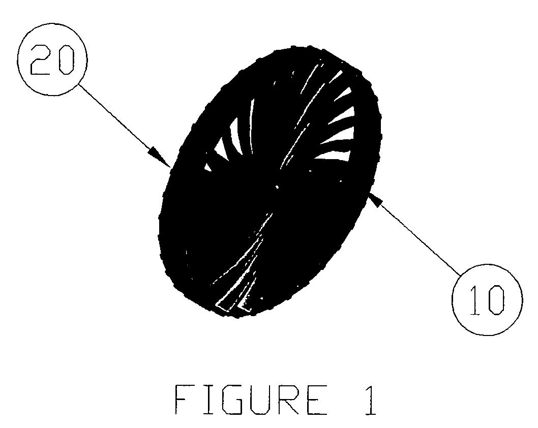
[0011] In accordance with the present invention, FIG. 1 shows a typical rotating engine stage. The ring 10 connecting the turbine blades contains high energy magnets 20. Compressor and Turbine stages are similar in design except for the shape of the blades.

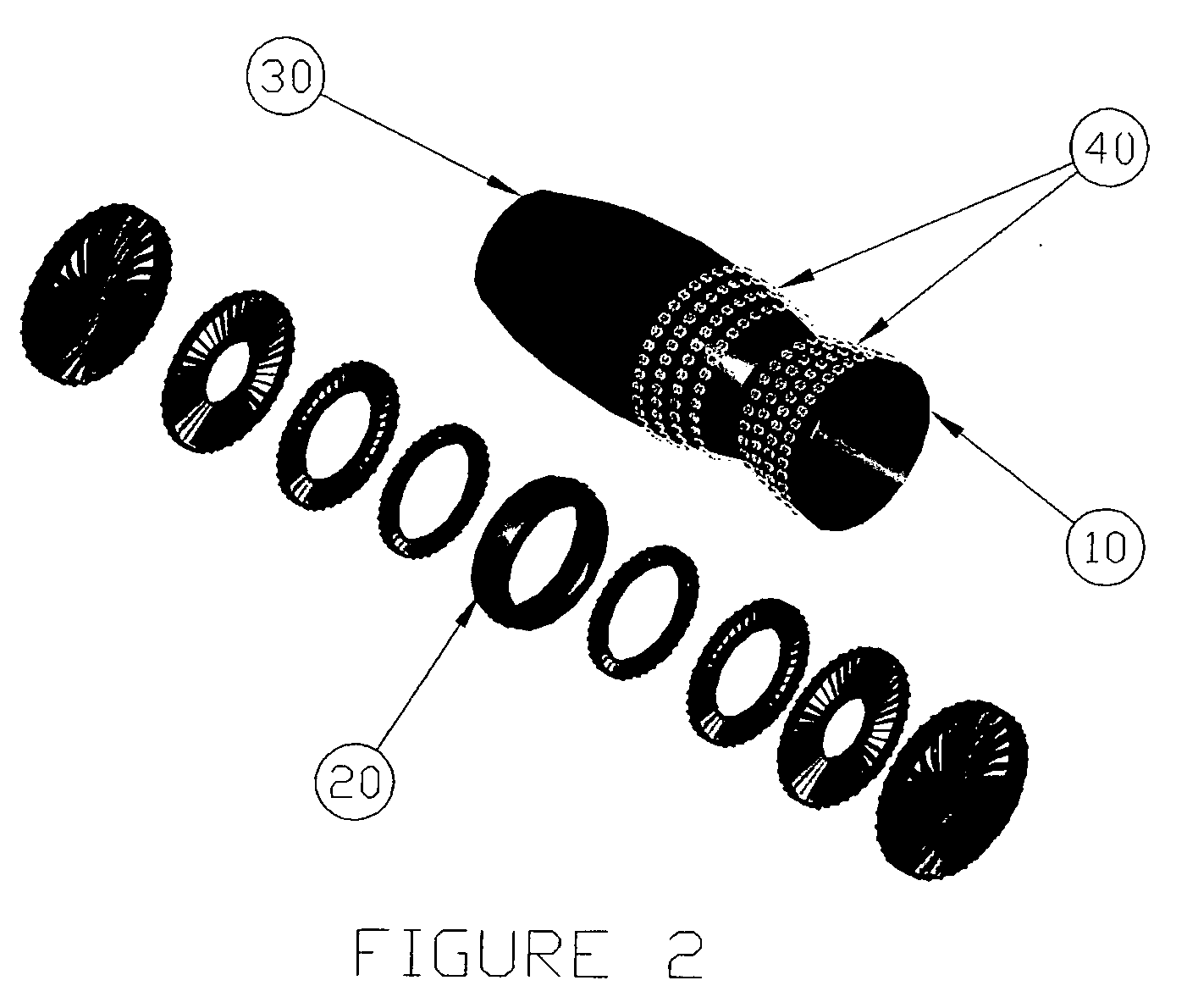
[0012] In accordance with the present invention, FIG. 2 shows a exploded view of a turbine engine. The inlet nozzle 10, combustor 20, and exhaust nozzle 30 are similar to other turbine engines. Windings 40 are located in the outer engine case. The combination of windings and hig...


PUM


Abstract

A machine for transferring power and producing electricity in a jet engine. with a ring connecting the tips of the compressor and turbine blades containing embedded high energy magnets, a set of coils for each rotating stage of the engine in the outer engine case, a power transfer and distribution system, a control system to regulate the engine and energy distribution, a ultracapacitor and efficient battery storage system, a set of magnetic bearings for each rotating stage, and a cooling system for the first couple turbine stages to keep the magnets from melting.

Description

BACKGROUND OF THE INVENTION [0001] This invention relates generally to the field of turbine engines and more specifically to a machine for transferring power and producing electricity in a turbine engine. [0002] Jet engines were invented back in the 1930's. They enable higher speeds in aircraft up to and above the speed of sound. The jet engine also provides a source of electrical power for the aircraft. Turbine engines are also used in ships, vehicles, and to generate electrical power. [0003] Magnets and the electric motor have been in use since the early 1900'S. The main enabling technology is the invention of high energy density magnets capable of generating large amounts of power in a small package. High power switching systems, compact transmission systems and new electrical storage systems are also enabling technologies. These technologies were developed in the 1980's and 1990's. [0004] Jet engines have used a shaft to connect the compressor and turbine. The stages are separat...

Claims


Application Information

Patent Timeline
Patent Type & Authority Applications(United States)
IPC IPC(8): F01D15/10H02K5/12H02K7/09
CPCF01D15/10F02C9/00F05D2240/51H02K7/1823Y02T50/671F16C39/063Y02T50/60
Inventor RANDALL, EDWARD RIGOR
Owner RANDALL EDWARD RIGOR
Learn More