Surface light source device and light guide using it and method therefor
a light source device and surface light source technology, applied in the direction of optical waveguide light guide, instruments, optics, etc., can solve the problems of insufficient suppression of bright lines by light shading members having a very small width, difficult to form light shading members at the desired position, and difficult to attach light shading members to the edge, etc., to prevent the generation of bright lines for a long time, reduce overall luminance, and reduce the effect of loss
Inactive Publication Date: 2007-02-08
MITSUBISHI RAYON CO LTD
View PDF11 Cites 22 Cited by
- Summary
- Abstract
- Description
- Claims
- Application Information
AI Technical Summary
Benefits of technology
[0014] The technique disclosed in Patent Document 4 resides in attaching a light shading member to an edge of the light incident end face of the light guide. Since a part of the light shading member covers the light incident end face, the light incident on the light incident end face is partly shaded so that the light introduced into the light guide from the primary light source decreases in amount by a value proportional to the size of the part covered by the light shading member. The entire luminance may therefore fall. Further, the part of the light incident on the light incident end face near the edge is shaded, though it would be introduced into and propagated through the light guide if the light shading member were not provided. Hence, dark lines are likely to appear in the display area. This technique which uses a light shading member having a very small width cannot sufficiently suppress the generation of bright lines. In practice, it is extremely difficult to attach a light shading member to the edge. It is difficult to form a light shading member at a desired position. Moreover, the light shading member, if attached to the edge, may easily be fall off.
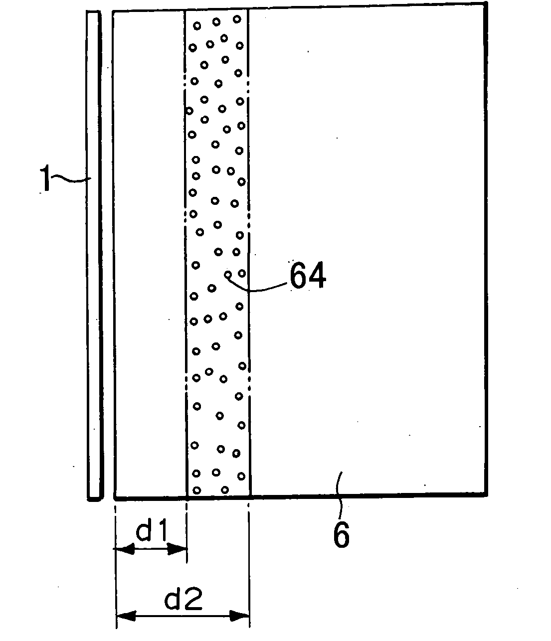
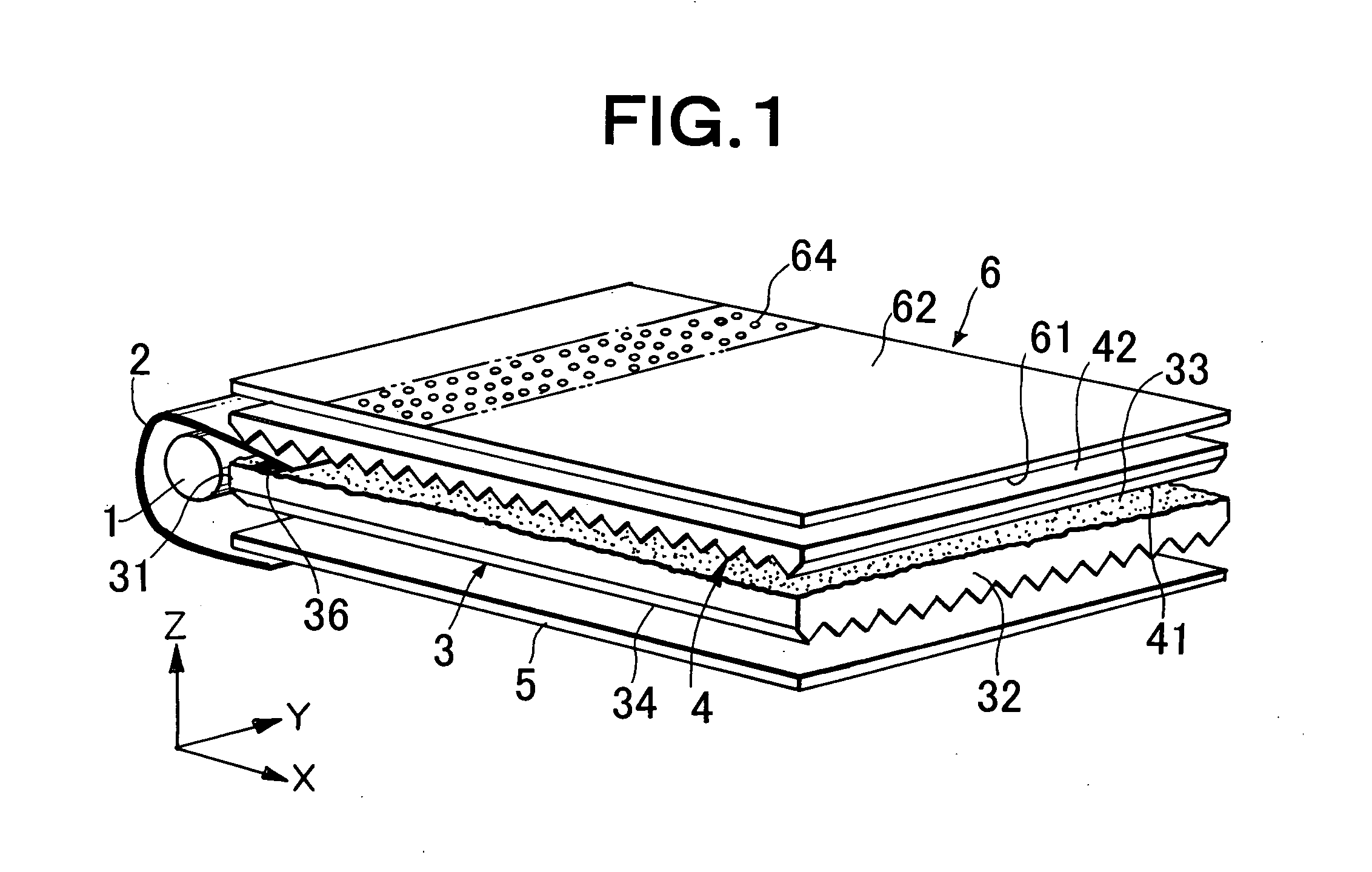
[0030] According to the present invention, a narrow light absorption band extending in parallel to the light incident end face of the light guide is provided on the light emitting face of the light guide and located near the light incident end face. Therefore, nothing shades or shields the light coming to the light incident end face from the primary light source. The light is introduced into the light guide from the primary light source with little loss. Hence, the overall luminance does not decrease or the light that should be introduced into the light guide is not shaded at all. No dark line will therefore be generated. Bright line or luminescent line or luminous line can be prevented from appearing in the vicinity of the light incident end face.
[0031] According to the present invention, the light absorption band is formed only on the light emitting face of the light guide. It is easier to form this band than otherwise. Moreover, the light absorption band thus formed hardly comes off. It can therefore prevent the generation of bright lines for a long time.
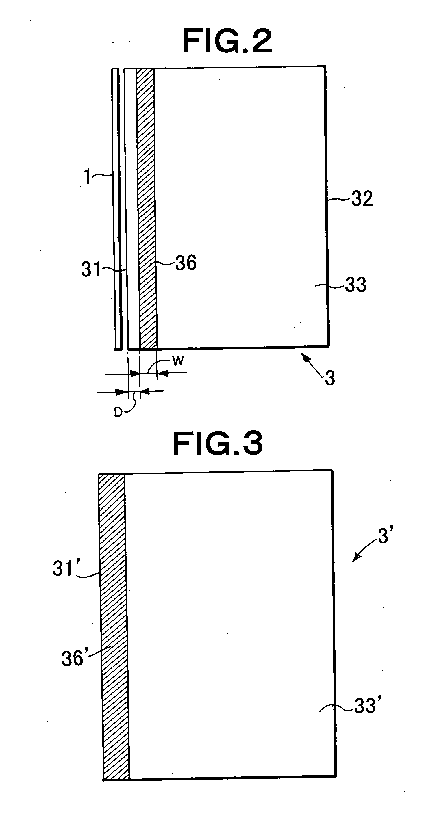
[0032] Furthermore, according to the present invention, a light absorption band part is formed on the light guide blank, and a shaving process is then performed on a light incident end face part of the light guide blank, thereby providing the light incident end face. This makes it easy to space the light absorption band by a distance of 0 μm from the light incident end face.
[0033] Still further, according to the present invention, ink dots are formed on the light emitting face of the light guide by means of ink-jet printing method. Thereafter, the ink dots are subjected to leveling and are thereby made larger. The ink dots are thereby combined with one another, forming a continuous ink layer. The ink-layer is cured, forming a light absorption band. Hence, the coupling of ink dots can be controlled by setting the leveling time in accordance with the viscosity of the ink. Thus, the surface condition of the light absorption band can be easily controlled.
Problems solved by technology
This technique which uses a light shading member having a very small width cannot sufficiently suppress the generation of bright lines.
In practice, it is extremely difficult to attach a light shading member to the edge.
It is difficult to form a light shading member at a desired position.
Moreover, the light shading member, if attached to the edge, may easily be fall off.
Thus, the light absorption layer can absorb the light, but insufficiently.
Method used
View moreImage
Smart ImageViewing Examples
Examples
example 1
[0147] 800 μm
EXAMPLE 2
[0148] 700 μm
example 3
[0149] 600 μm
EXAMPLE 4
[0150] 500 μm
example 5
[0151] 400 μm
EXAMPLE 6
[0152] 300 μm
Login to View More PUM
 Abstract
A planar light source device capable of preventing the occurrence of a luminescent line in the vicinity of a light incident end face without interrupting an incident light incoming from a primary light source and entering at a light incident end face, and being not likely to cause a decrease in incident light quantity, that is, without lowering entire luminance and producing dark lines to be caused when light to be originally guided is shaded. A platy light guide (3) that guides light emitted from a primary light source (1) and has a light incident end face (31) for receiving light from the primary light source (1) and a light emitting face (33) for outputting the guided light which is formed with a light absorption zone (36) extending along the light incident end face (31) and having a width of 50 to 1000 μm, and a side edge closer to the light incident end face (31) of the light absorption zone (36) is up to 300 μm away from the light incident end face (31). The light incident end face (31) is so constructed that light emitted from the primary light source (1) is incident as far as the boundary with the light emitting face (33).
Description
TECHNICAL FIELD [0001] The present invention relates to a planar light source device of an edge-light type and a light guide for use in the light source device. More particularly, the invention relates to a planar light source device designed to reduce non-uniformity in luminance distribution observed as streaks, i.e., bright lines and / or dark lines, which exist near a light incident end face of a light guide facing a primary light source and which extend along the light incident end face of the light guide. The invention also relates to a light guide for use in the planar light source device and a method of manufacturing the light guide. [0002] A planar light source device according to the present invention is fit for use as backlight in, for example, liquid crystal display devices. BACKGROUND ART [0003] In recent years, liquid crystal display devices have been used widely in various fields, as monitors for portable notebook-type personal computers, display units of liquid crystal ...
Claims
Login to View More Application Information
Patent Timeline
 IPC IPC(8): G02B6/10F21V8/00
CPCG02B6/0011G02B6/00G02B6/0001G02F1/1335
Inventor YAMASHITA, TOMOYOSHIMURAYAMA, YOSHIAKINOZAKI, YOSHIHITO
Owner MITSUBISHI RAYON CO LTD
Features
- R&D
- Intellectual Property
- Life Sciences
- Materials
- Tech Scout
- Unparalleled Data Quality
- Higher Quality Content
- 60% Fewer Hallucinations
Learn More Browse by: Latest US Patents, China's latest patents, Technical Efficacy Thesaurus, Application Domain, Technology Topic, Popular Technical Reports.
© 2025 PatSnap. All rights reserved.Legal|Privacy policy|Modern Slavery Act Transparency Statement|Sitemap|About US| Contact US: help@patsnap.com


