Storage controller super capacitor adaptive life monitor

Active Publication Date: 2007-02-08
DOT HILL SYST
View PDF23 Cites 80 Cited by
  • Summary
  • Abstract
  • Description
  • Claims
  • Application Information

AI Technical Summary

Benefits of technology

[0016] The present invention samples the temperature and voltage of a capacitor pack of a storage controller during an operating interval and normalizes the interval using a ratio of a warranted lifetime of the capacitor pack to a known lifetime of the capacitor pack at the sampled temperature and voltage. When the capacitor pack no longer has sufficient capacity to store a predetermined amount of energy at a normal operating voltage, then the capacitor pack has reached its end of life, or lifetime. In one embodiment, the warranted lifetime is based upon the amount of energy required to supply power to the storage controller for backing up a volatile write cache to a non-volatile memory, such as a FLASH memory, during the loss of main power. The storage controlle

Problems solved by technology

That is, not only must the specified system data be written to the disk drives, but some of the disk drives may also have to be read before the user data and redundant data can be written to the disks, which, without the benefit of posted-writes, may make the write latency of a RAID controller even longer than a non-RAID controller.
However, posted-write operations make the system vulnerable to data loss in the event of a power failure.
This is because the cache memory is a volatile memory that loses the user data when power is lost and the data has not yet been written to the disk drives.
Although the battery greatly reduces the likelihood that user data will be lost, because the energy stored in the battery is finite, the possibility still exists that the battery energy will run out before main power can be restored, in which case the user data will be lost.
The minimum length of time the battery must supply power to the cache memory varies among users of RAID systems; however, many consumers require at least 72 hours in the event a power failure occurs on a weekend.
However, there are some well-known limitations associated with the use of batteries in this application.
First, batteries are a relatively expensive component of the RAID controller.
Second, for many of the relevant battery technologies the ability of the battery to hold a charge begins to degrade within two or three years, which is typically less than the expected lifetime of the RAID controller.
This adds further cost to the RAID controller.
Third, the operating temperature range of batteries outside of which their lifetime and performance degrade significantly is relatively small.
Fourth, after the battery has been drained due to a main power outage, the RAID controller must operate in lower performance write-through cache mode until the battery is re-charged, and the re-charge time of batteries is relatively long.
Fifth, as the size of cache memories increases, so does the amount of energy the battery must provide during the main power outage; given contemporary battery energy densities, the size of the battery required to provide the required amount of energy may exceed the available space within the RAID controller.
When the energy source no longer has the capacity to store enough energy to perform its intended function, such as to supply power to perform a backup operation, it is said to have reached its end of life, or its lifetime has expired.
Therefore, the simple real-time clock technique used to monitor battery lifetime is inadequate for capacitors in many applications because the variability in capacitor lifetime may pose an unacceptable risk of data loss for write-caching storage controllers.
However, this method is undesirable for write-caching storage controller applications, since it would require the write cache to be placed into write-through mode during the discharging / recharging process in order to avoid the potential loss of write cache data due to the inability to perform the backup operation in the event of a main power loss.
Furthermore, unlike a battery, the capacitor pack may not be field-replaceable, and the storage controller manufacturer may warrant a lifetime of the capacitor pack to the consumer, or user, of the storage controller.

Method used


Image

  • Storage controller super capacitor adaptive life monitor
  • Storage controller super capacitor adaptive life monitor
  • Storage controller super capacitor adaptive life monitor

Examples


Embodiment Construction

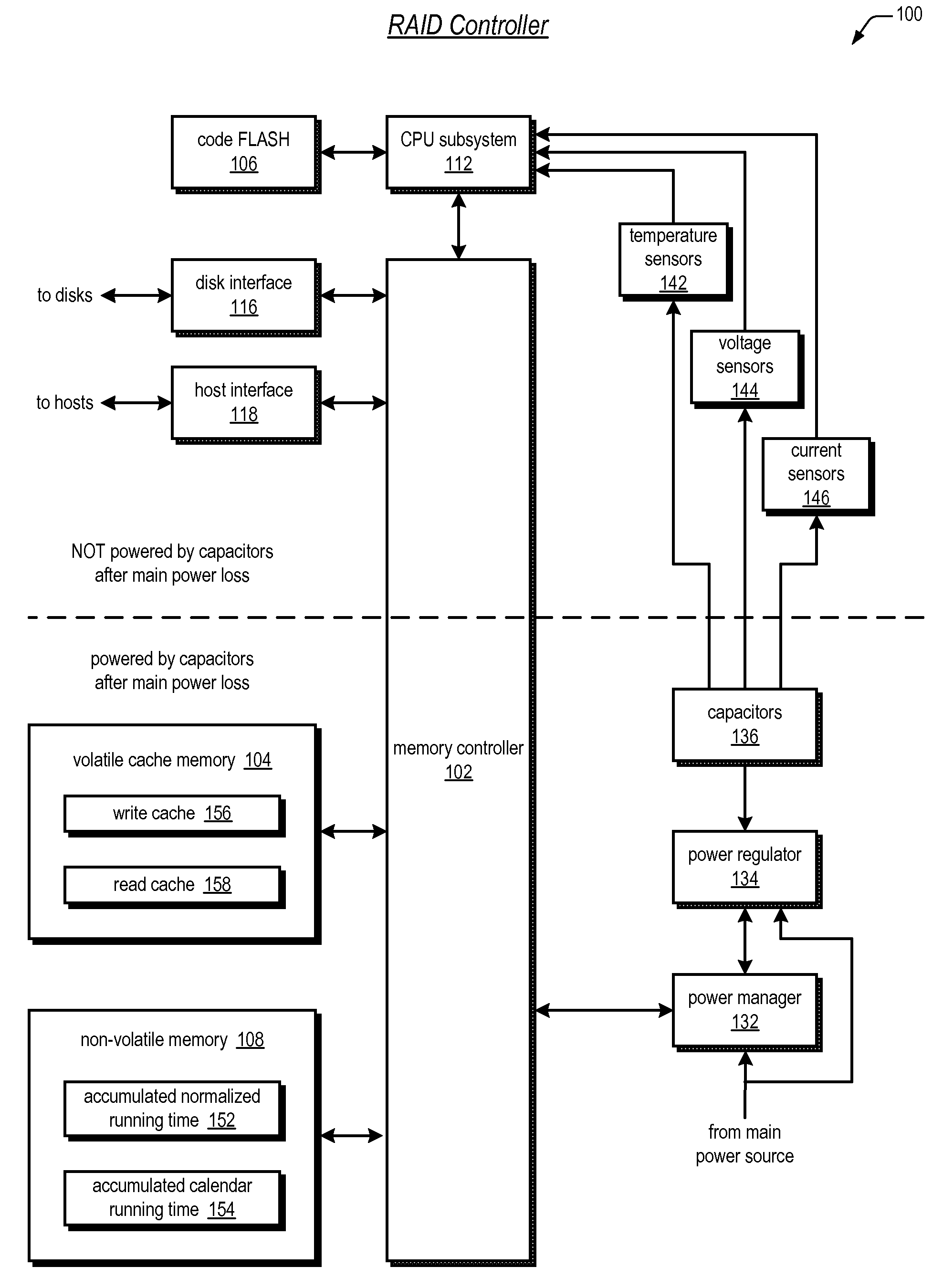
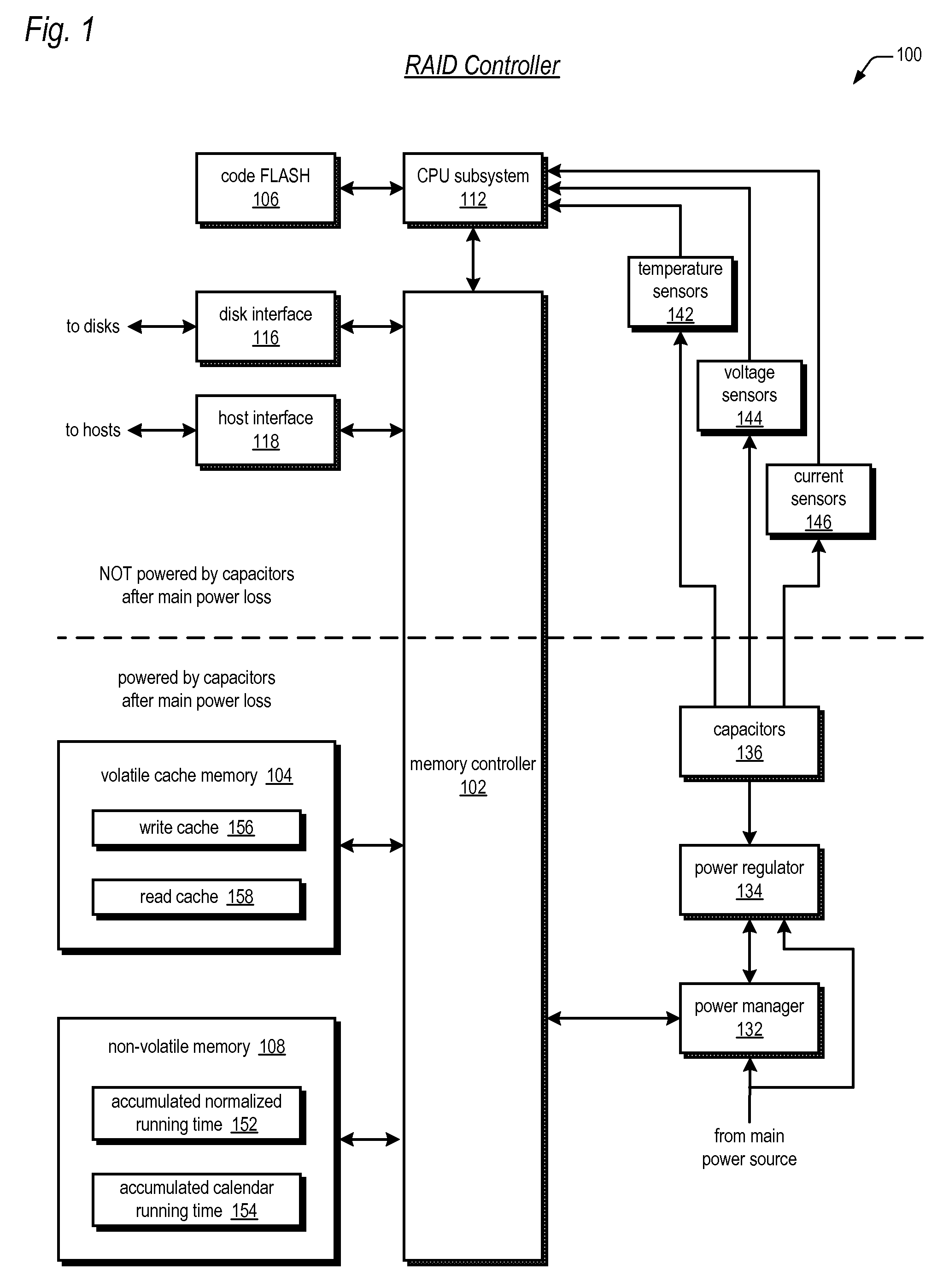
[0034] Referring now to FIG. 1, a block diagram illustrating a RAID controller 100 according to the present invention is shown. In one embodiment, the RAID controller 100 may be one of a pair of active-active redundant fault-tolerant RAID controllers for providing high data availability. In the event of a failure of one RAID controller 100, such as the failure to flush posted-write data from volatile memory to non-volatile memory as described herein, the system may failover to the other RAID controller 100. The RAID controller 100 includes one or more capacitors for supplying power to selected portions of the RAID controller 100 circuits during the loss of main power for enabling a memory controller thereof to quickly and efficiently flush the posted-write data from a cache memory to a non-volatile memory. Advantageously, the RAID controller 100 periodically samples the temperature and voltage of the capacitors and adaptively calculates an effective age of the capacitors using lifet...


PUM


Abstract

A storage controller has a capacitor pack for storing energy to supply during a main power loss, a temperature sensor that senses the capacitor pack temperature, and a CPU, which repeatedly: receives the temperature during an interval over which the capacitor pack is operated, determines a lifetime over which the capacitor pack would have a capacity to store at least a predetermined amount of energy if operated at the temperature during the lifetime, normalizes the interval by a ratio of a warranted lifetime of the capacitor pack relative to the determined lifetime, and adds the normalized interval to an accumulated normalized running time. The operating voltage of the capacitor pack may also sampled and used to determine the lifetime. The predetermined amount of energy may be for backing up a volatile write cache to a non-volatile memory in response to the loss of main power.

Description

CROSS REFERENCE TO RELATED APPLICATION(S) [0001] This application claims priority to U.S. Provisional Application No. 60 / 705,997, filed Aug. 4, 2005, which is hereby incorporated by reference. [0002] This application is related to the following U.S. non-provisional applications. Ser. No.(Docket No.)Filing DateTitle                    —STORAGE CONTROLLER SUPER(CHAP.0133)CAPACITOR DYNAMIC VOLTAGETHROTTLING                    —STORAGE CONTROLLER DYNAMIC(DH.0136)WRITE CACHE SIZE ADJUSTMENTBASED ON SUPER CAPACITORCAPACITYFIELD OF THE INVENTION [0003] The present invention relates in general to the field of using a capacitor pack as a re-chargeable backup energy supply in storage controllers, and particularly to lifetime monitoring of the capacitor pack. BACKGROUND OF THE INVENTION [0004] Redundant Array of Inexpensive Disk (RAID) systems have become the predominant form of mass storage systems in most computer systems today that are used in applications that require high performance, la...

Claims


Application Information

Patent Timeline
IPC IPC(8): G06F11/00
CPCG06F1/28G06F11/3058G06F11/1441G06F1/30
Inventor PECONE, VICTOR KEYWANG, YUANRU FRANK
Owner DOT HILL SYST
Why Eureka
Try Eureka