

Hybrid amplitude-phase grating diffusers
- Summary
- Abstract
- Description
- Claims
- Application Information
AI Technical Summary
Benefits of technology
Problems solved by technology
Method used
Image

Examples
Embodiment Construction
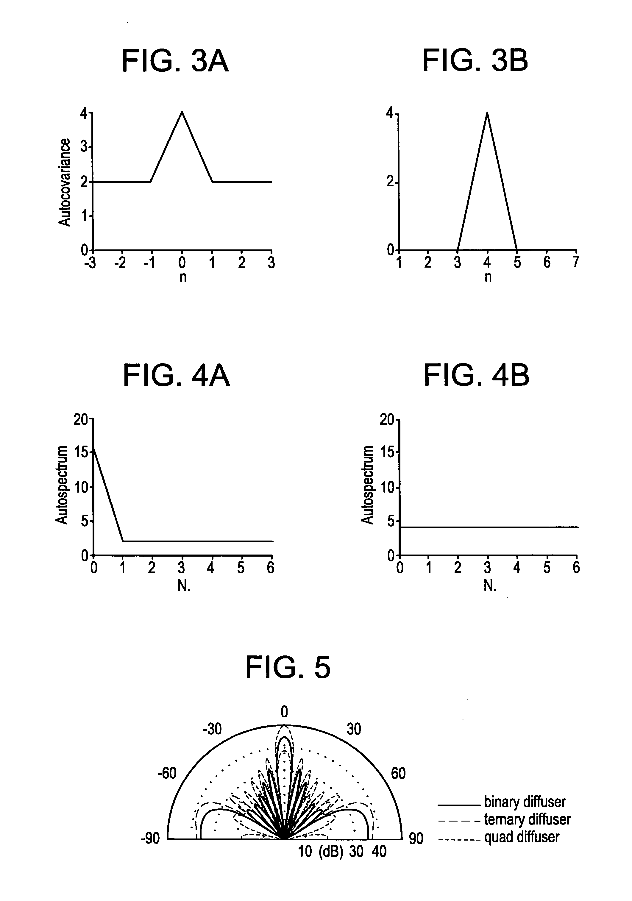
Short One Dimensional Ternary Sequences
[0054] To compare the performance of unipolar binary and ternary sequences, it is necessary to construct some diffusers for comparison, and for this, sequences with the best patch order are needed. For diffusers with a small number of patches, it is possible to find the best sequences by an exhaustive search of all possible combinations. It is well established that the autocovariance (or autocorrelation function) of the surface reflection factors relates to the evenness of the scattering in the far field, with the autocovariance, which most resembles the delta function being best. Consequently, a computer may be tasked to search though all possible combinations of the reflection coefficients and find the one with the best autocovariance function. To do this search, the computer requires a number to judge the quality of the sequence, and this is provided by a merit factor. The merit factor used to judge the quality of the autocovariance functi...
PUM
 Abstract
Description
Claims
Application Information