
Method for the manufacture of a three-dimensional molding

a three-dimensional molding and manufacturing method technology, applied in the direction of additive manufacturing, electric/magnetic/electromagnetic heating, additive manufacturing, etc., can solve the problems of stress build-up despite the adjustment of laser beams, and achieve the reduction of the risk of crack formation, high surface quality of molding, and improved surface composition and strength

Inactive Publication Date: 2007-02-15
TRUMPF WERKZEUGMASCHINEN GMBH & CO KG
View PDF1 Cites 67 Cited by
  • Summary
  • Abstract
  • Description
  • Claims
  • Application Information

AI Technical Summary

Benefits of technology

[0007] For that reason, the invention aims at creating a method for the manufacture of a three-dimensional molding, facilitating a non-deforming manufacture of overhang regions of a three-dimensional molding.
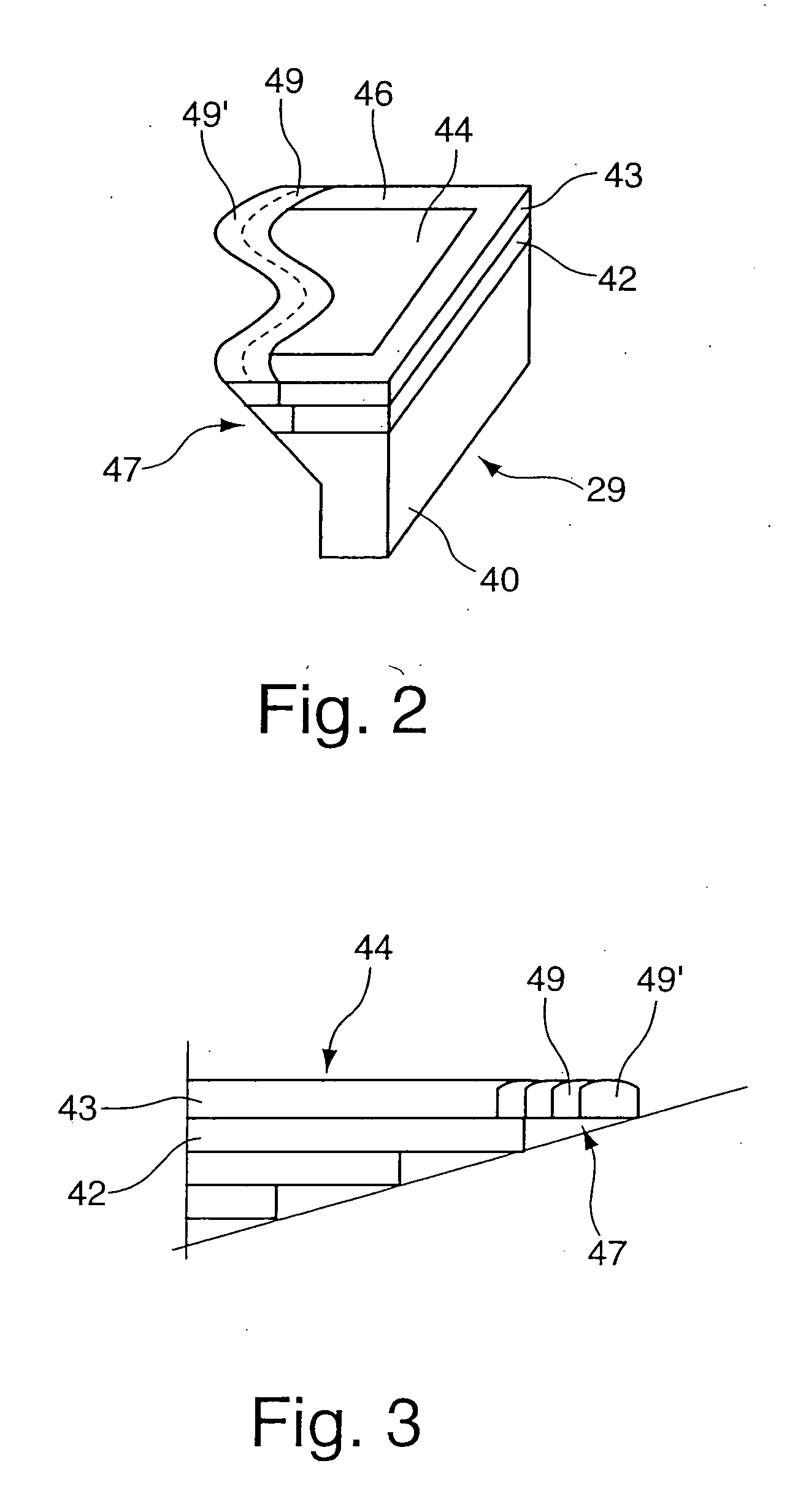
[0009] The method according to the invention, which is based on overhang radiation true to contours, enables the manufacture of an overhang region with at least minimum stress and minimum deformation. The overhang region is arranged adjacent to a region that has already solidified in a coherent manner. A first contour trace following the outer contour of the overhang region is placed at the transition from the already coherently solidified region to the overhang region. The first contour trace of the overhang region is made irrespective of the radiation strategies used beforehand. The contour traces are built up in the free material powder and have a high degree of overlapping in relation to the already solidified region. The placement of one or more contour traces next to each other in a contour-adjusted manner in order to produce an overhang region ensures that the layer to be solidified is homogeneous and also enables filigree structures.
[0010] According to an advantageous embodiment of the method, it is provided that the beam for the production of the contour trace is directed onto material that has not solidified yet, with an overlapping degree of at least 50 percent of the trace width in relation to the preceding contour trace, or to the already coherently solidified region. The high degree of overlapping allows diminishing of internal stresses, because an essential part of the previously built contour trace that has already solidified or of the already coherently solidified region is fused once again.
[0012] According to a further advantageous embodiment of the method, it is provided that the layer to be built from powder material is subdivided in a core region, an outer contour region and an overhang region, wherein a matching radiation strategy is allocated to each region. In the core region and the outer contour region, it is, for example, possible to select radiation strategies which solidify as large an area of the layer as possible in the core region within a short time, while generating a high surface quality of the molding in the outer contour region. In the overhang region, adjustment of the radiation strategy allows the development of a homogeneous transition, so that the risk of formation of cracks is reduced. As a result, the radiation strategy can be adjusted to individual regions for filigree structures, thereby producing fine-structure geometries. For example, crosshatched radiation or onion radiation can be used for the core region and the outer contour region, wherein the individual radiation strategies can also be mixed with each other within each of the regions. Irrespective of these radiation strategies in the core region and / or the outer contour region, the overhang radiation provided for the overhang region is true to contours, in order to allow uniform and homogeneous formation of the overhang region. This permits to achieve an improved surface composition and strength.
[0014] According to a further advantageous embodiment of the invention, it is provided that the radiation strategy for any one region is selected irrespective of the radiation strategies in the further region. This allows to achieve a high flexibility in the manufacture of the three-dimensional molding which may comprise various regions with different qualities and structures in its composition.

Problems solved by technology

Onion radiation, which starts with an initial contour line corresponding to the edge contour of the layer to be built, is to disadvantage in that, through the transitions from powder material to solidified material, stresses are built up despite an adjustment of laser beam parameters.

Method used


Image

  • Method for the manufacture of a three-dimensional molding
  • Method for the manufacture of a three-dimensional molding
  • Method for the manufacture of a three-dimensional molding

Examples


Embodiment Construction

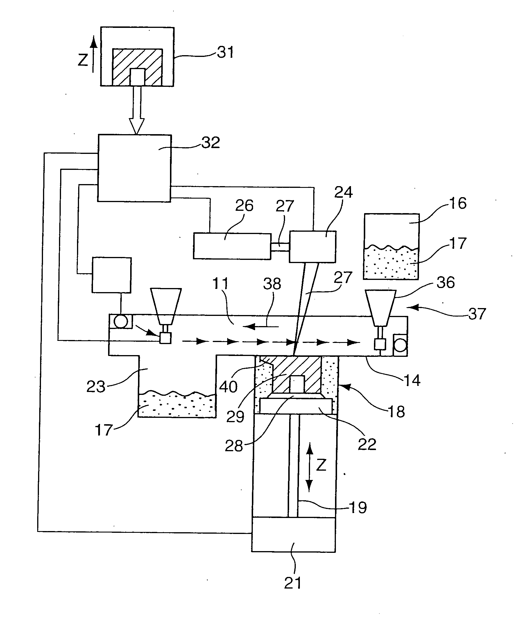
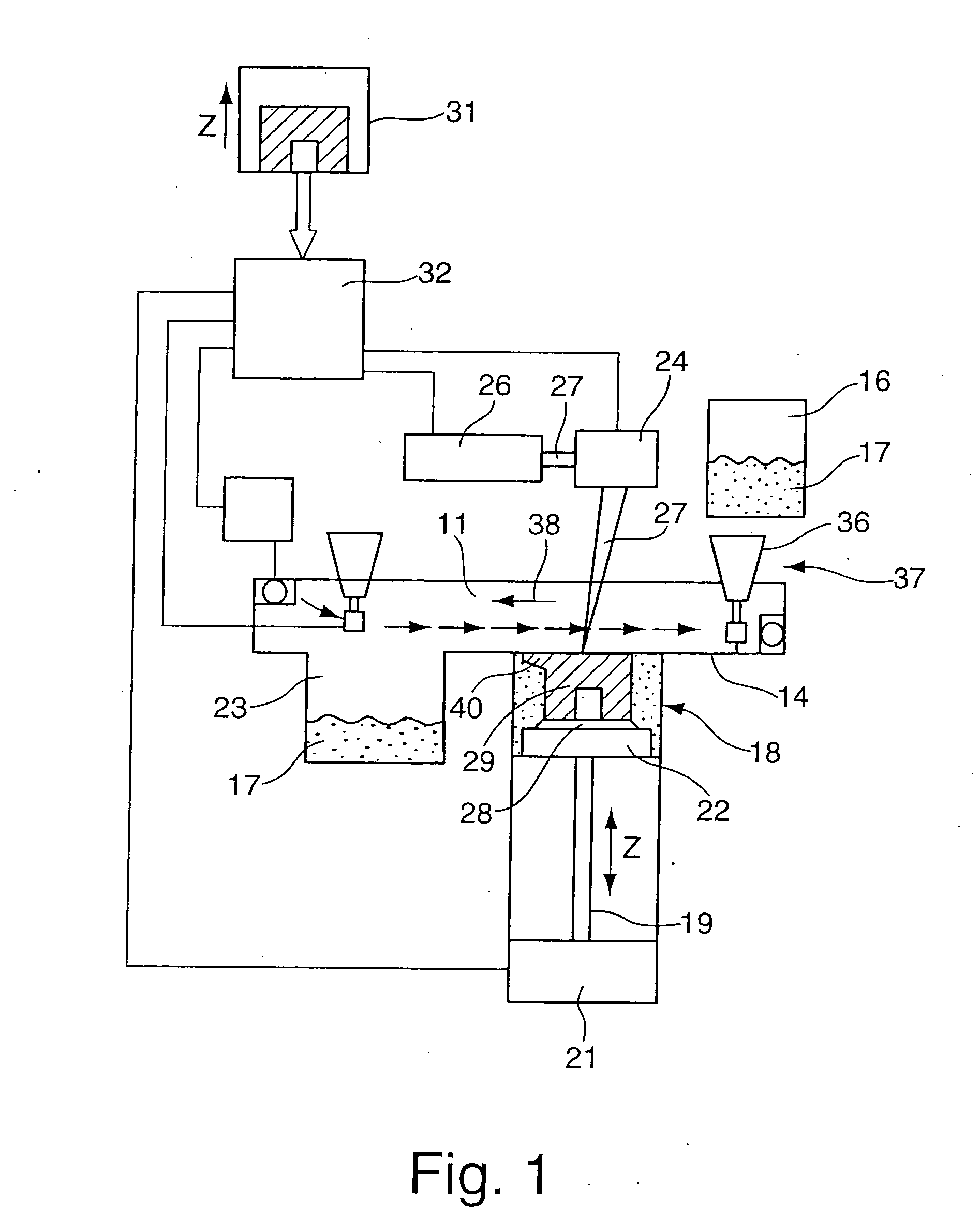
[0020]FIG. 1 shows an apparatus for generative processing with laser radiation, particularly for selective laser melting, such as described in DE 198 53 978 C1. This apparatus comprises a process chamber 11. A storage tank 16 which is filled with material powder 17 is provided above a bottom area 14 of the process chamber 11. The material powders used may, for example, be ferrous metals, such as steel; non-ferrous metals, such as titanium or aluminum; or other materials, such as composite materials or plastic materials. A build chamber 18 which accommodates a build platform 22 driven by a drive 21 via a lifting screw 19 ends in the bottom area 14 from below. A base plate 28 is arranged on the build platform 22 in a detachable manner, wherein a molding 29 is built on the base plate 28. A collection tank 23 for the material powder 17 is provided next to the build chamber 18. A displacement assembly 24 directing a laser beam 27 generated by a laser 26 onto the build platform 22 or base...


PUM

PropertyMeasurementUnit
angleaaaaaaaaaa
widthaaaaaaaaaa
diameteraaaaaaaaaa

Abstract

The invention relates to a method for the manufacture of a three-dimensional molding (29), wherein the molding (29) is generated from a solidifiable powder material by consecutively solidifying individual layers through the effect of radiation (27), while generating a new layer by exposing traces that are arranged adjacent to each other to radiation, wherein, in order to form an overhang region (47), a contour trace (49) is formed on a coherently solidified region and on a powder material (17) that has not solidified yet, the contour trace (49) is adjusted to an outer contour at least in the region of transition from the solidified region to the powder material (17) that has not solidified yet, and the at least one further contour trace (49′) adjusted to the outer contour is formed of non-solidified material (17) while comprising a high overlapping degree in relation to the previously formed contour trace (49).

Description

BACKGROUND OF THE INVENTION [0001] The invention relates to a method for the manufacture of a three-dimensional molding, wherein the molding is generated from a solidifiable powder material by consecutively solidifying individual layers through the effect of radiation, e.g. laser radiation. [0002] DE 43 09 524 C2 has disclosed a method for the manufacture of a three-dimensional molding wherein each layer is disintegrated in an inner core region and an outer enveloping region. The radiation strategies selected in the core region and the enveloping region are differing in order to generate different properties of either region. The radiation in the core region is such that the deformation of the object during and after solidification is at a minimum, whereas the radiation in the enveloping region is provided for generating as smooth and precise a surface as possible. To achieve this, the enveloping region is defined by subtracting individual regions of the core region from the overall...

Claims


Application Information

Patent Timeline
Patent Type & Authority Applications(United States)
IPC IPC(8): B29C35/08
CPCB29C67/0077B22F3/1055B29C64/153B33Y80/00Y02P10/25B22F10/28B22F10/366B22F10/385
Inventor WUST, FRANK PETERSCHMID, MICHAEL
Owner TRUMPF WERKZEUGMASCHINEN GMBH & CO KG
Learn More