Sighted device operable in visible-wavelength or electro-optical/visible-wavelength sighting modes

Active Publication Date: 2007-02-15
RAYTHEON CANADA LTD
View PDF5 Cites 34 Cited by
  • Summary
  • Abstract
  • Description
  • Claims
  • Application Information

AI Technical Summary

Benefits of technology

[0007] The present approach provides a sighted device wherein the sight may be operated in either the visible-wavelength range or in a mixed mode that utilizes both electro-optical imaging and visible-wavelength imaging. The user may choose to use only visible-wavelength imaging, or to modify the visible image with electro-optical processing to improve viewability, or to increase wavelength capability such as by using mixed infrared and visible imaging, or to place non-image information in the field of view of the user. In the event that the electronic imaging fails, the backup is

Problems solved by technology

In the work leading to the present approach, the inventor has observed that the available electro-optical sights have the drawback that their functionality is lost in the event

Method used


Image

  • Sighted device operable in visible-wavelength or electro-optical/visible-wavelength sighting modes
  • Sighted device operable in visible-wavelength or electro-optical/visible-wavelength sighting modes
  • Sighted device operable in visible-wavelength or electro-optical/visible-wavelength sighting modes

Examples


Embodiment Construction

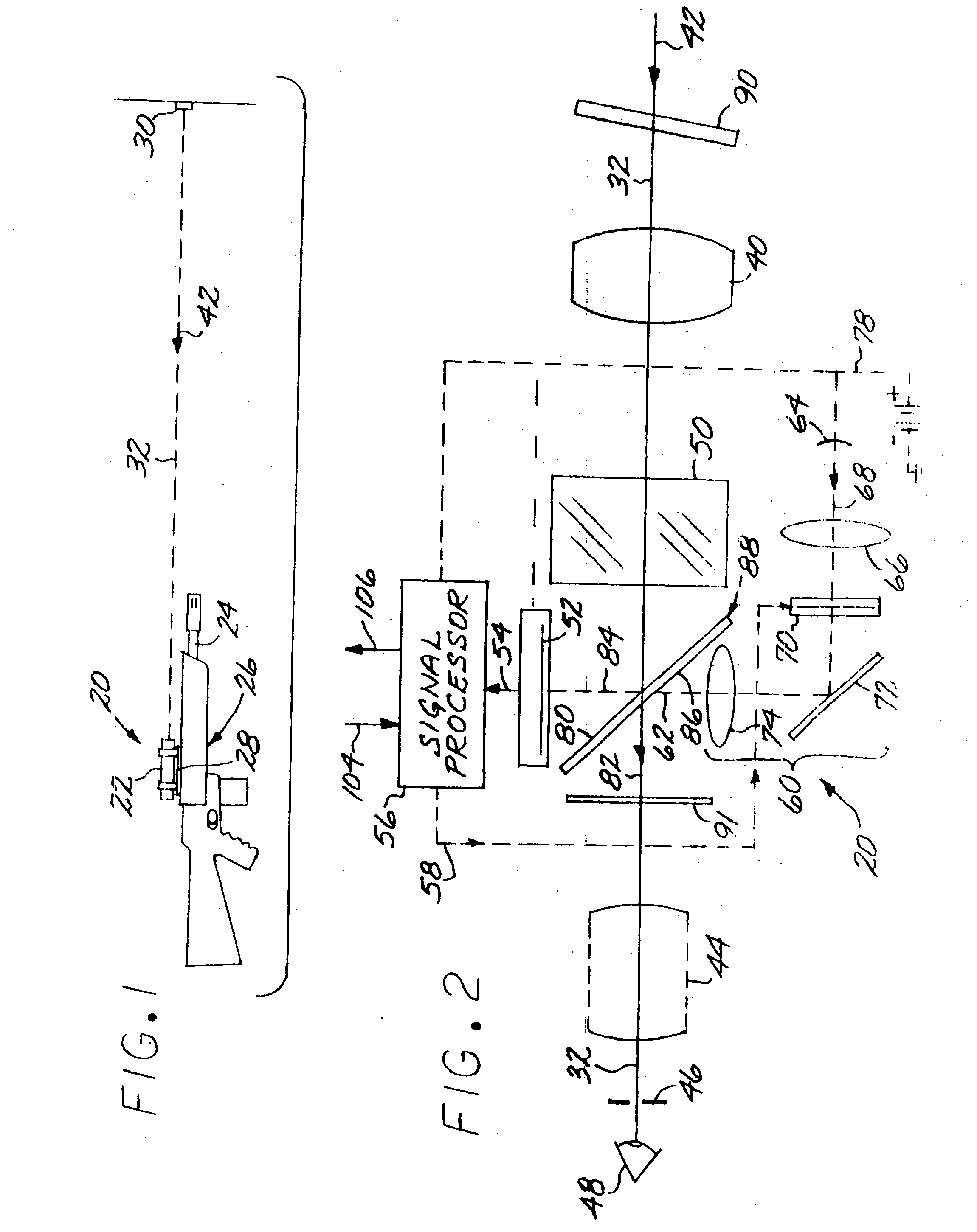
[0017]FIG. 1 depicts a sight 20 having an elongated, generally cylindrical housing 22. The sight 20 is affixed to a barrel 24 (in this case through the barrel-support) of a rifle (or other aimed device) to form a sighted device 26. There is an adjustable attachment 28 that allows the entire sight 20 to be moved as a unit relative to the remainder of the sighted device 26, in this case relative to the barrel 24, for fine adjustment. The user of the sighted device 26 aims the sighted device 26 and the sight 20 at a distant target 30 along a line of sight, which is also an optical axis 32 of the sight 20. The sight 20 aids the user in aiming the sighted device 26 at the target 30 of interest.

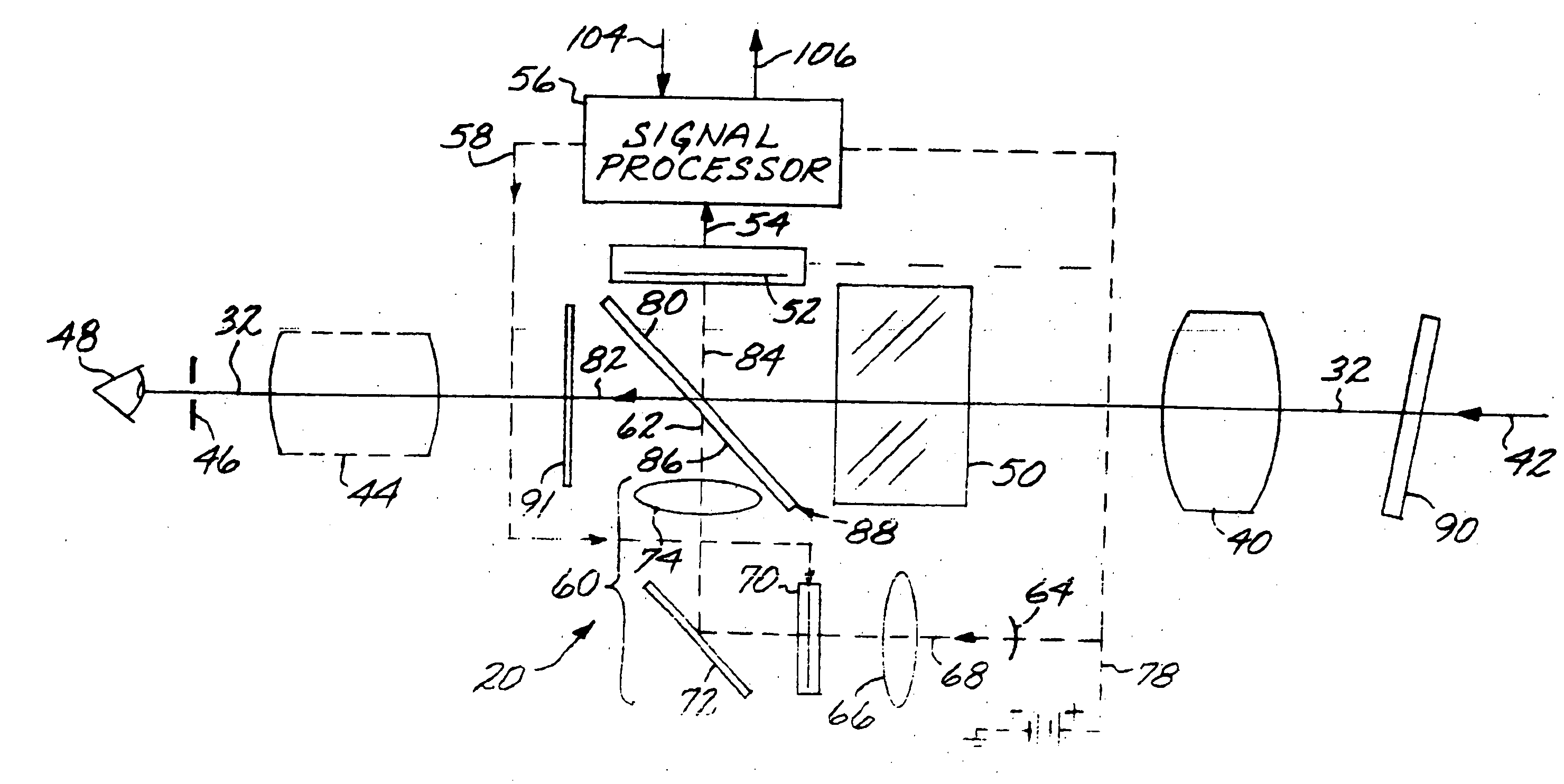
[0018]FIG. 2 schematically illustrates the interior components of the sight 20 that are within the housing 22. The sight 20 comprises an objective lens 40 lying on the optical axis 32 of the sight 20 so that an input beam 42 is coincident with the optical axis 32. (Within the interior of the sight...


PUM


Abstract

A sighted device has a sight that includes an objective lens lying on an optical axis of the sight so that an input beam is coincident with the optical axis, an eyepiece lens lying on the optical axis, an imaging detector having a detector output signal, a signal processor that receives the detector output signal from the imaging detector, modifies the detector output signal, and has a processor output signal, and a video display projector that receives the processor output signal and has a video display projector output. An optical beam splitter lies on the optical axis. The beam splitter allows a first split subbeam of the input beam to pass to the eyepiece lens and reflects a second split subbeam of the input beam to the imaging detector. An optical mixer mixes the first split subbeam and the video display projector output prior to the first split subbeam passing through the eyepiece lens.

Description

[0001] This invention relates to a sighted device such as a rifle having a telescopic sight and, more particularly, to such a sighted device that may be operated with either visible-wavelength-only imaging, or in a mixed mode that includes electro-optical and also visible-wavelength imaging. BACKGROUND OF THE INVENTION [0002] A hand-carried rifle has a sight that aids the user of the rifle in aiming the rifle at the target. In one approach, fixed (sometimes termed “iron”) sights are affixed to the upper side of the barrel of the rifle and are aligned to aid the user to point the barrel. The fixed sights operate in the visible wavelength range and at unity magnification. [0003] A rifle may instead be provided with a telescopic sight that magnifies the visible-range image of the target using conventional lenses. The telescopic sight makes it easier to aim the rifle at a distant target because the target is larger when viewed through the telescopic sight. The telescopic sight normally ...

Claims


Application Information

Patent Timeline
IPC IPC(8): G02B23/00
CPCF41G1/38H04N5/74H04N5/33H04N5/23293G02B23/12H04N5/7441H04N5/7458H04N23/55
Inventor SCHOLZ, ROBERT J.
Owner RAYTHEON CANADA LTD
Why Eureka
Try Eureka