Digital Controller Based Power Factor Correction Circuit

a technology of power factor and digital controller, applied in pulse generators, pulse techniques, instruments, etc., can solve the problems of power factor lowering, power waste, and power factor wasting

Inactive Publication Date: 2007-02-15
SILICON LAB INC
View PDF4 Cites 69 Cited by
  • Summary
  • Abstract
  • Description
  • Claims
  • Application Information

AI Technical Summary

Problems solved by technology

But this excessive current, which does not contribute to low power, wastes power in the winding resistance of the input power source and a resistance of the input power line.
In the field of switching regulators, any circuit configuration which causes input line current to be non-sinusoidal or even sinusoidal but out of phase with the sinusoidal input voltage or to have harmonics of the line voltage results in a lowered power factor and consequent waste of the power.

Method used


Image

  • Digital Controller Based Power Factor Correction Circuit
  • Digital Controller Based Power Factor Correction Circuit
  • Digital Controller Based Power Factor Correction Circuit

Examples


Embodiment Construction

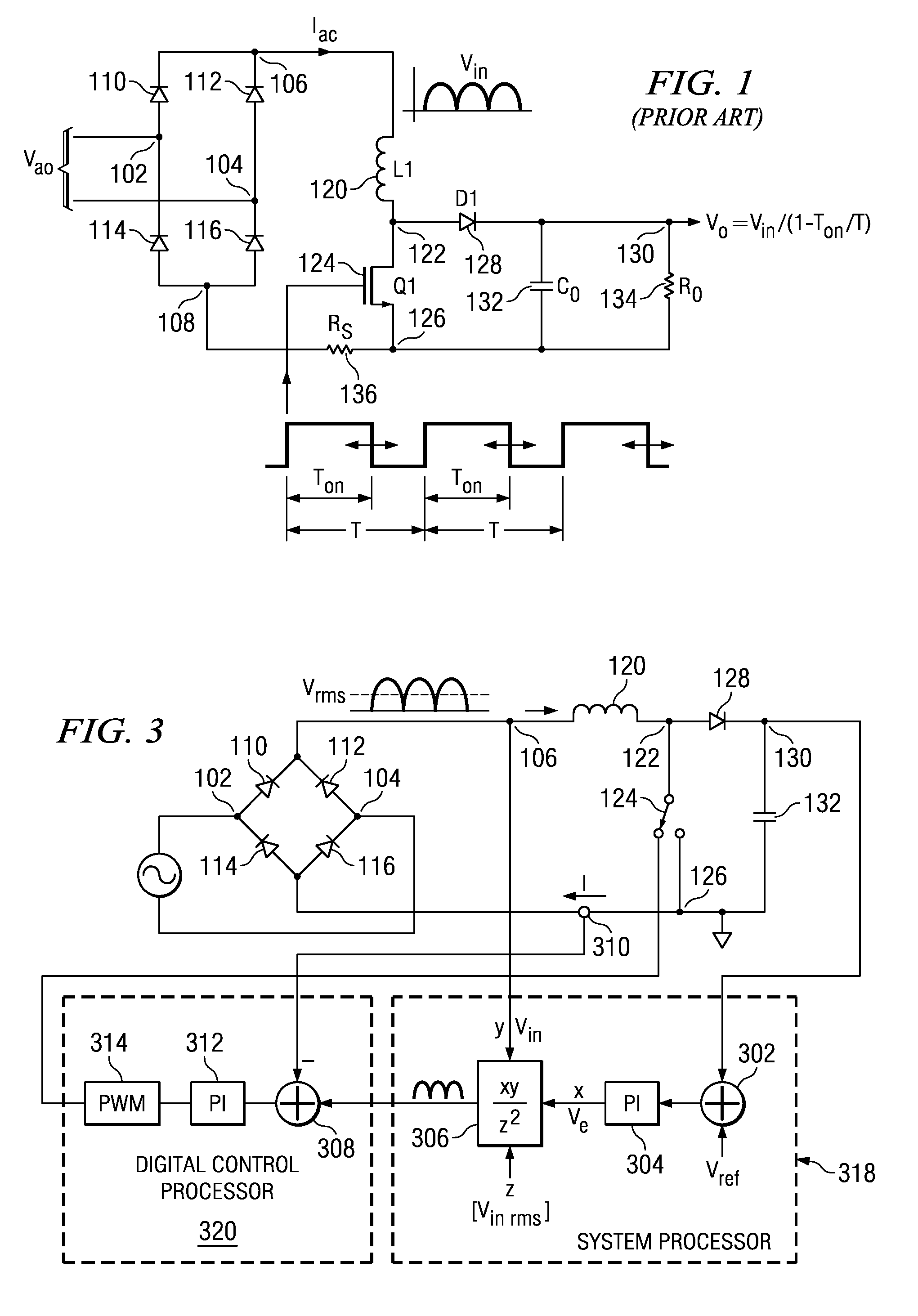
[0022] Referring now to FIG. 1, there is illustrated a prior art boost regulator with power factor correction (PFC). A full wave rectifier is provided between two input nodes 102 and 104 that receive an AC voltage and provide a rectified voltage between two nodes 106 and 108, node 106 being the VIN voltage which has a current Iac associated therewith. A first diode 110 is connected between node 102 to node 106 and a second diode 112 is connected between node 104 and 106, diodes 102 and 112 having the cathodes thereof connected to node 106. Similarly, a diode 114 is connected between node 102 and node 108 and a diode 116 is connected between node 104 and 108, the cathodes of diodes 114 and 116 connected to respective nodes 102 and 104. The voltage at node 106 is a rectified voltage that has an input zero crossing. These are half sinusoids that are then operable to drive a continuous-mode boost converter. This converter is comprised of an inductor 120 connected between node 106 and a ...


PUM


Abstract

A power factor correction circuit utilizes a digital controller string comprised of an analog-to-digital converter, which is input to a digital compensator followed by a pulse width modulation circuit for generating a switching pulse. The loop current in a regulator circuit such as a boost regulator is sensed and input to one side of a differential analog-to-digital converter, the other side thereof providing a digital reference current. This digital reference current is derived from comparing the input AC voltage to the regulator with the DC output voltage and processing these two voltages with a PFC algorithm to provide this reference voltage.

Description

CROSS-REFERENCE TO RELATED APPLICATIONS [0001] This application claims priority in U.S. Provisional Patent Application Ser. No. 60 / 678,353 filed on May 6, 2005 entitled “DIGITAL CONTROLLER BASED POWER FACTOR CORRECTION CIRCUIT,” which is incorporated in its entirety herein by reference.TECHNICAL FIELD OF THE INVENTION [0002] The present invention pertains in general to power factor controllers (PFC), and more particularly, to a power factor controller utilizing a digital control string. BACKGROUND OF THE INVENTION [0003] The term “power factor” is borrowed from elementary AC circuit theory. When a sinusoidal AC power source feeds either an inductive or a capacitive load, the load current is also sinusoidal but lags or leads the input voltage by some angle “x” for an rms input voltage Vi and rms input current Ii, the “apparent power” taken from the lines is ViIi. However, the actual power delivered to the load is only ViIi cos(x) is only the component of input current which is in pha...

Claims


Application Information

Patent Timeline
Patent Type & Authority Applications(United States)
IPC IPC(8): H03B1/00
CPCH02M1/42Y02B70/12H03K17/0822H02M3/157Y02B70/10
Inventor LEUNG, KA Y.ALFANO, DONALD E.FOSLER, ROSS MARTIN
Owner SILICON LAB INC
Why Eureka
Try Eureka