
Phase chip frequency-bins optical code division multiple access

a phase chip frequency and optical code technology, applied in the field of optical communication, can solve the problems of difficult for one party in a conversation to hear the other party, their conversation will drown out the other conversation, and the number of users is quite limited in fdma and tdma

Inactive Publication Date: 2007-02-15
TELCORDIA TECHNOLOGIES INC
View PDF25 Cites 42 Cited by
  • Summary
  • Abstract
  • Description
  • Claims
  • Application Information

AI Technical Summary

Problems solved by technology

However, FDMA and TDMA are quite limited in the number of users and / or the data rates that can be supported for a given transmission band.
Ordinarily, it is very difficult for one party in a conversation to hear the other party if many conversations occur simultaneously.
For example, if one pair of speakers is excessively loud, their conversation will drown out the other conversations.
Moreover, when different pairs of people are speaking in the same language, the dialogue from one conversation may bleed into other conversations of the same language, causing miscommunication.
In general, the cumulative background noise from all the other conversations makes it harder for one party to hear the other party speaking.
The increased number of users in the transmission band merely increases the noise to contend with.
However, as a practical matter, there is some threshold at which the “signal-to-noise” ratio becomes unacceptable.
This signal-to-noise threshold places real constraints in commercial systems on the number of paying customers and / or data rates that can be supported.
Each receiving station is provided with optical receiving equipment capable of regenerating an optical pulse when it receives a pattern of chips coded in accordance with its own unique sequence but cannot regenerate the pulse if the pulse is coded with a different sequence or code.

Method used


Image

  • Phase chip frequency-bins optical code division multiple access
  • Phase chip frequency-bins optical code division multiple access
  • Phase chip frequency-bins optical code division multiple access

Examples


Embodiment Construction

[0041] This detailed description incorporates by reference herein the disclosures of commonly assigned U.S. application Ser. No. ______ (Telcordia APP No. 1548 / TELCOR 1.0-003), filed Jan. 31, 2005 and titled “Multi-Wavelength Optical CDMA With Differential Encoding And Bipolar Differential Detection.”

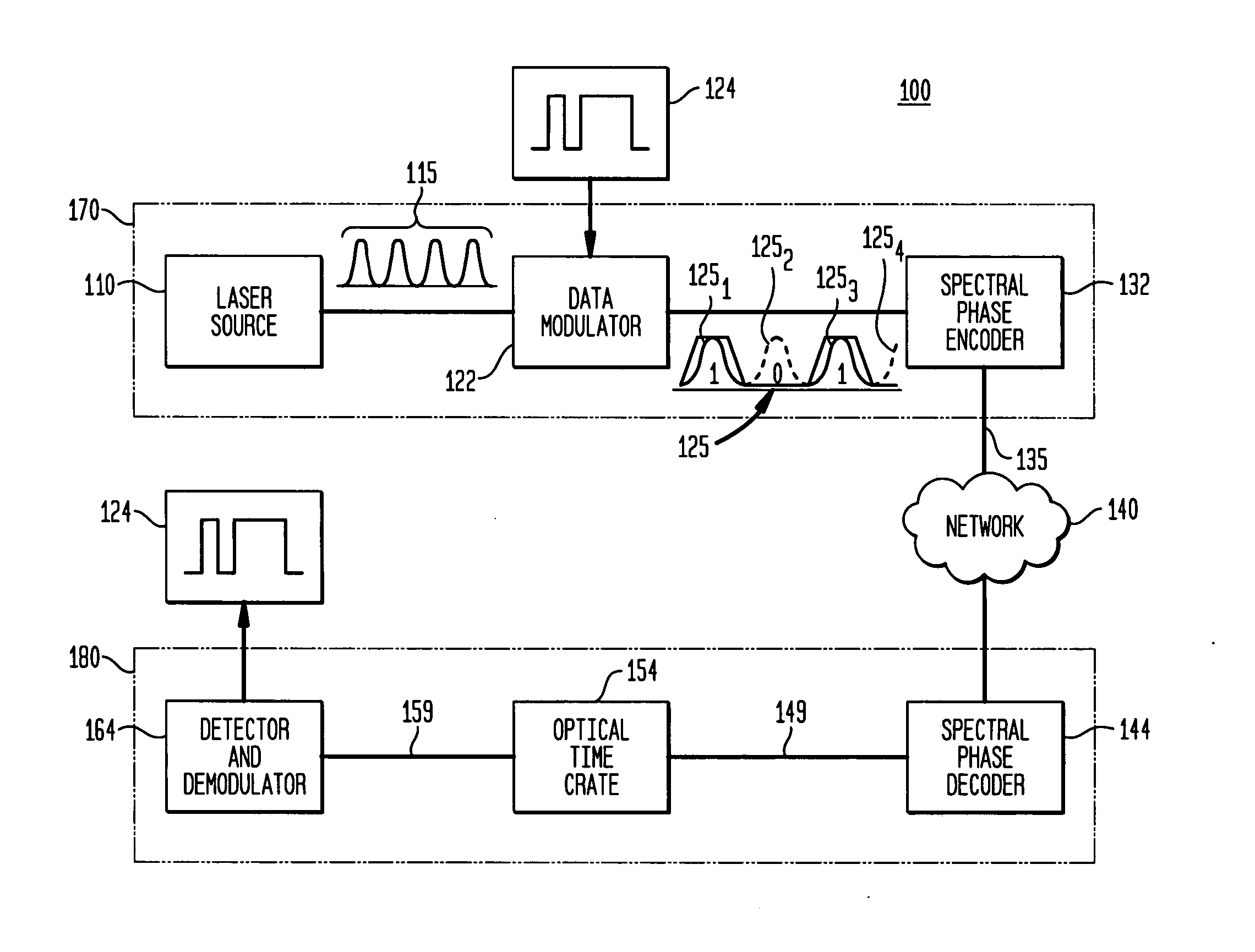
[0042]FIG. 1 illustratively depicts a system 100 in accordance with an aspect of the present invention. The system comprises a laser source 110 that generates a sequence of optical pulses 115 that are fed to a data modulator 120. The data modulator 122 also receives a data stream 122 that is used to modulate the sequence of optical pulses 115. The modulation data preferably comprises a digital data stream generated by a subscriber or user station 124. In a preferred embodiment, the data modulator 122 comprises an ON / OFF keyed data modulator wherein a “1” symbol or bit in the digital data stream corresponds to the presence of an optical pulse and a “0” symbol or bit corresponds to the ab...


PUM


Abstract

Apparatus and system for transmitting and receiving optical code division multiple access data over an optical network. The apparatus comprises a spectral phase decoder for decoding the encoded optical signal to produce a decoded signal, a time gate for temporally extracting a user signal from the decoded signal, and a demodulator that is operable to extract user data from the user signal. The system preferably comprises a source for generating a sequence of optical pulses, each optical pulse comprising a plurality of spectral lines uniformly spaced in frequency so as to define a frequency bin, a data modulator associated with a subscriber and operable to modulate the sequence of pulses using subscriber data to produce a modulated data signals and a Hadamard encoder associated with the data modulator and operable to spectrally encode the modulated data signal to produce an encoded data signal.

Description

CROSS-REFERENCE TO RELATED APPLICATIONS [0001] This application is related to U.S. application Ser. No. ______ (Telcordia APP No. 1548 / TELCOR 1.0-003), filed Jan. 31, 2005 and titled “Multi-Wavelength Optical CDMA With Differential Encoding And Bipolar Differential Detection,” assigned to the assignee of the present application, the disclosure of which is incorporated herein by reference.STATEMENT REGARDING FEDERALLY SPONSORED RESEARCH [0002] Funding for research was partially provided by the Defense Advanced Research Projects Agency under federal contract MDA972-03-C-0078. The federal government has certain rights in this invention.BACKGROUND OF THE INVENTION [0003] The present invention relates to optical communication and, more particularly, to optical code division multiple access (OCDMA) communication networks. [0004] Various communications schemes have been used to increase data throughput and to decrease data error rates as well as to generally improve the performance of comm...

Claims


Application Information

Patent Timeline
IPC IPC(8): H04B10/00
CPCH04J14/007H04B10/505
Inventor ETEMAD, SHAHABTOLIVER, PAULJACKEL, JANET LEHRMENENDEZ, RONALD CHARLESGALLI, STEFANOBANWELL, THOMAS CLYDEDELFYETT, PETER
Owner TELCORDIA TECHNOLOGIES INC
Learn More