Method of manufacturing a wind turbine blade, wind turbine blade, front cover and use of a front cover

a manufacturing method and technology for wind turbine blades, applied in the direction of propellers, propulsive elements, water-acting propulsive elements, etc., can solve the problems of increasing the cost of blades such as grounding and polishing, and achieve the effects of easy and reliable operation, light weight and cost efficiency

Inactive Publication Date: 2007-02-15
VESTAS WIND SYST AS
View PDF7 Cites 120 Cited by
  • Summary
  • Abstract
  • Description
  • Claims
  • Application Information

AI Technical Summary

Benefits of technology

[0057] When, as stated in claim 33, said front cover is made in glass fibre material or a similar fibre material such as carbon or aramid fibre material reinforcing an epoxy or polyester resin, plastic material or combinations of the mentioned materials, a preferred embodiment of the front cover has been achieved. Especially, as the front cover is both resilient to weather conditions, durable, light weighted and cost efficient.
[0058] When, as stated in claim 34, said front cover being made in a metal plate material such as aluminium or similar light metal plates with welded or adhered distance means...

Problems solved by technology

In the construction of the wind turbine blade it is thus not necessary to involve aftertreatment comprising ti...

Method used


Image

  • Method of manufacturing a wind turbine blade, wind turbine blade, front cover and use of a front cover
  • Method of manufacturing a wind turbine blade, wind turbine blade, front cover and use of a front cover
  • Method of manufacturing a wind turbine blade, wind turbine blade, front cover and use of a front cover

Examples


first embodiment

[0132]FIGS. 7a to 7c illustrate a first method of manufacturing a wind turbine blade including a front cover according to the invention.

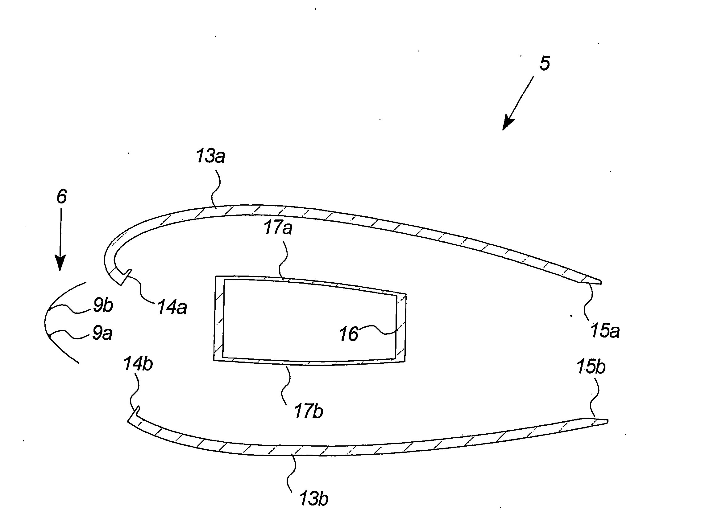
[0133] The front cover 6 corresponds to the front cover of FIG. 4 with one distance means 9 positioned at the middle of the centre section C. Further, the front cover comprises two flap sections F with an adhesive layer 11a, 11b on the inner surface.

[0134]FIG. 7a illustrates the front of the wind turbine blade 5 and the front cover positioned opposite each other.

[0135]FIG. 7b illustrates how the distance means 9 initially meet the front of the wind turbine blade. The surface of the distance means may in an embodiment include adhesive means establishing a first connection between the front cover and the wind turbine blade.

[0136] It is further illustrated that the flap sections do not connect with the sides of the wind turbine blade as they extend in a wider angle than the blade shape. However, the extension angle may also be less than the blade re...

second embodiment

[0147]FIGS. 7d to 7f illustrate a second method of manufacturing a wind turbine blade including a front cover according to the invention.

[0148]FIG. 7d illustrates a front cover comprising two symmetrically positioned distance means 9a, 9b but not comprising adhesive layers on the inner surfaces of the flap sections F.

[0149]FIG. 7e illustrates the positioning of the front cover on the front of the wind turbine blade. With adhesive means on the distance means it is possible to arrange the front cover in a stable position on the wind turbine blade.

[0150]FIG. 7f illustrates the closing of the space underneath the front cover with a line of tape T connecting the outer surface of the front cover and the side of the wind turbine blade. The space is filled with an adhesive mass 18 after the closure of the sides with tape and the crossings between the front covers—as described above—have been established.

third embodiment

[0151]FIGS. 7g and 7h illustrate a third method of manufacturing a wind turbine blade including a front cover according to the invention.

[0152]FIG. 7g illustrates a front cover comprising two symmetrically positioned distance means 9a, 9b and adhesive layers on the inner surfaces of the flap sections F. The flap sections are forced to meet the sides of the wind turbine blade by bending the front cover over the two distance means before being filled with the adhesive mass 18 (as illustrated in FIG. 7h).

[0153] It shall be emphasized that the space closure may comprise a number of holes, in addition to the filling holes, such as holes ventilating the adhesive mass during the curing. The holes may be closed at a following aftertreatment of the wind turbine blade.

[0154]FIG. 8 illustrates a flow chart of the manufacturing of a wind turbine blade including a preferred embodiment of a front cover according to the invention.

[0155] The manufacturing method includes the steps: [0156] a) Cas...


PUM

PropertyMeasurementUnit
Lengthaaaaaaaaaa
Lengthaaaaaaaaaa
Lengthaaaaaaaaaa

Abstract

The invention relates to a method of manufacturing a wind turbine blade, said method comprising the steps of: casting at least two wind turbine shells and preferably one or more load bearing structures, forming a wind turbine blade structure including at least two longitudinal joints by adhering said at least two wind turbine shells and said one or more load bearing structures together, forming one or more front covers to a shape substantially corresponding to said wind turbine blade structure or sections hereof, positioning said one or more front covers in relation to said wind turbine blade structure, and fastening said one or more front covers to said wind turbine blade structure with adhering means. The invention also relates to a wind turbine blade, front cover and the use of a front cover as a unit for supplementary mounting on a wind turbine blade.

Description

BACKGROUND OF THE INVENTION [0001] The invention relates to a method of manufacturing a wind turbine blade, a wind turbine blade according to the preamble of claim 10, a front cover according to the preamble of claim 19 and use of a front cover. DESCRIPTION OF THE RELATED ART [0002] Modern wind turbines usually comprise a rotor with a considerable diameter size, as illustrated in FIG. 1. The wind turbine blades for modern wind turbines are approaching lengths of 50 metres and more. [0003] In order to create wind turbine blades that are capable of withstanding the significant forces of the wind as well as their own weight, the blades are constructed with two glass fibre shells and one or more internal glass fibre load-bearing beams, ribs etc., all adhered to each other. [0004] The wind turbine blades have to undergo an aftertreatment, as the surface of the wind turbine shells needs smoothing so that the wind will not be slowed down or make any noise when it moves across the surface o...

Claims


Application Information

Patent Timeline
IPC IPC(8): B64C11/24B29C63/22F03D1/06
CPCB29C63/22B29C65/485B29C65/546B29C65/7826B29C65/7855B29C66/1122B29C66/54B29L2031/082B29L2031/085F03D1/0675F05B2240/30Y02E10/721B29C65/54B29C66/4722B29C65/542B29C66/5326B29C66/303B29C66/12841B29C65/5042B29C66/1142B29C66/1282B29C65/4835B29C65/00B29C66/128B29C66/7212B29C66/71B29C66/721B29C66/742B29C66/7422Y02E10/72Y02P70/50B29C65/483B29K2307/04B29K2309/08B29K2277/10B29K2067/00B29K2063/00B29K2077/10
Inventor HIBBARD, PAUL
Owner VESTAS WIND SYST AS
Why Eureka
Try Eureka