Method and device for locating magnetic implant source field

a magnetic implant and source field technology, applied in the field of magnetic implant methods, can solve the problems of difficult without proper imaging guidance to provide even a reasonable guess, the determination of this movement can be a problem, and it is difficult to accurately and reliably locate the magnetic surgical implant, and achieve the effect of accurately and reliably locating the magnetic surgical implan

Inactive Publication Date: 2007-02-15
RITTER ROGERS C +3
View PDF99 Cites 96 Cited by
  • Summary
  • Abstract
  • Description
  • Claims
  • Application Information

AI Technical Summary

Benefits of technology

[0015] It is a further object of this invention to provide a method and apparatus for accurately and reliably locating a magnetic surgical implant without requiring x-ray, ultrasonic, or fluoroscopic imaging devices.
[0016] It is another object of this invention to provide a method and apparatus for accurately and reliably locating a magnetic surgical implant by using a magnet that simultaneously serves the functions of guiding a magnetic implant and locating it.
[0017] It is yet a further object of the invention to provide a method and apparatus for locating a magnetic surgical implant that permits a wide range of unobstructed motion to be provided to an external magnet or electromagnet for guiding the magnetic surgical implant.
[0018] It is a still further object of the invention to provide a method and apparatus for locating a magnetic surgical implant that is not subject to interference caused by the presence of the external magnet.

Problems solved by technology

Determination of this movement can be a problem, because the implanted device can, in general, move in three-dimensional space inside the patient.
However, fluoroscopic imaging can be subject to interference from the magnet, itself.
In difficult interference situations, it is difficult without proper imaging guidance to provide even a reasonable guess as to a correct direction for the magnet axis to obtain field alignment with the intended path.
(supra) is one attempt to minimize the “blindness” of the approach just described, but the Yodh et al. approach still relies on operator judgment and vision, and is subject to such error.
(supra) can be used to provide such guidance, it is difficult in such systems to provide a combined guiding force and force-applying field gradient in the same desired direction.

Method used


Image

  • Method and device for locating magnetic implant source field
  • Method and device for locating magnetic implant source field

Examples


Embodiment Construction

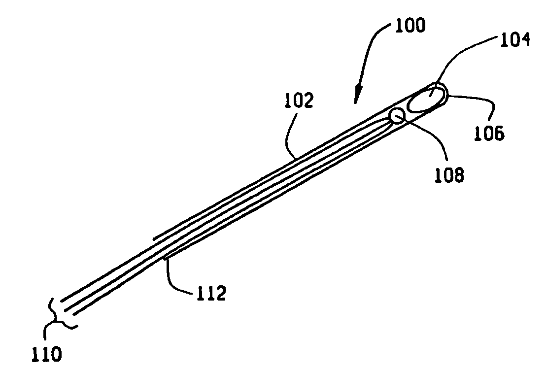
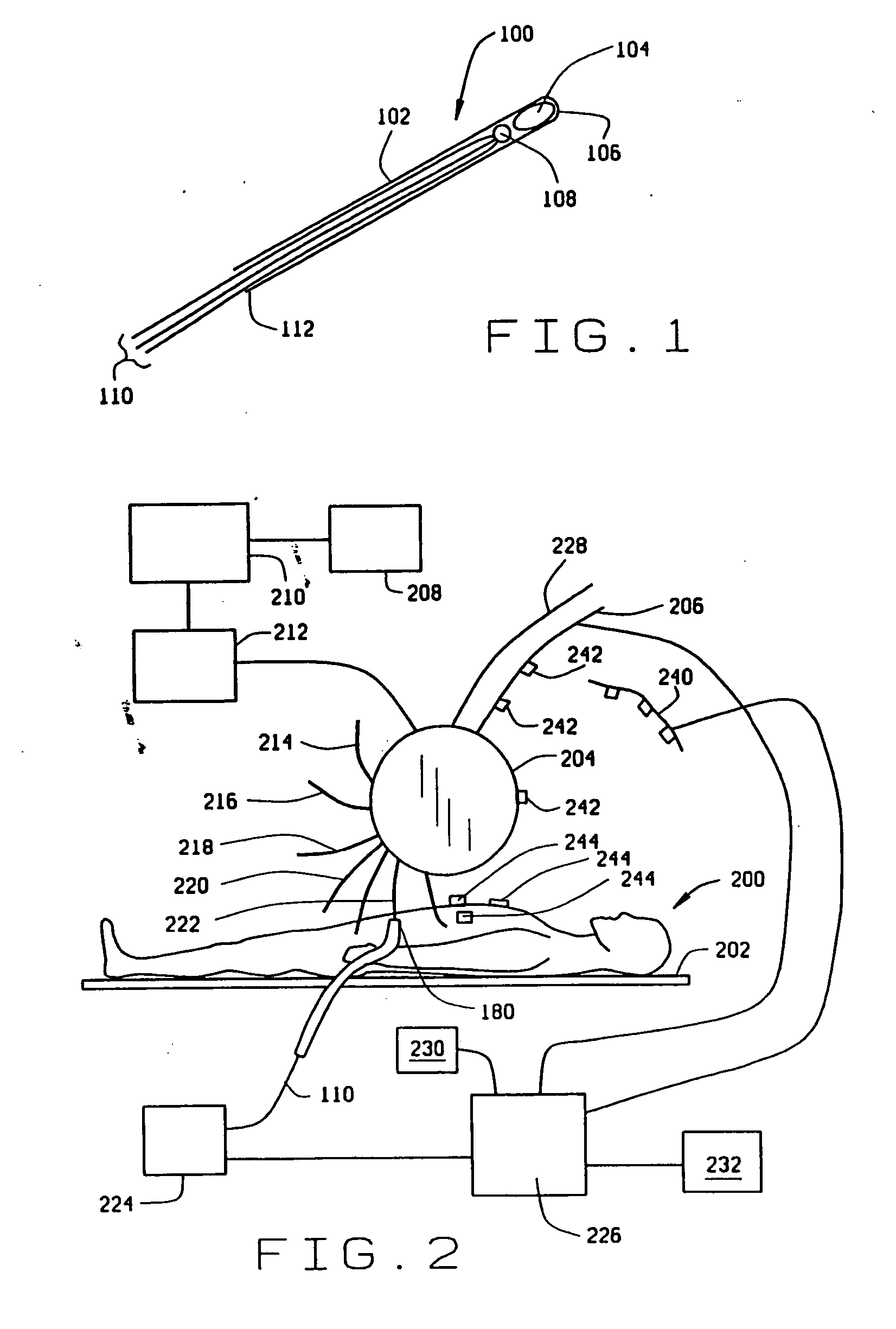
[0021]FIG. 1 is a diagram illustrating an embodiment 100 of an inventive device in accordance with a first aspect of the invention. This device comprises a flexible probe 102, which may be an endoscope or a catheter tube. A magnetic seed 104 of permanent magnetic, or at least a permeable material, is located near an end 106 of the flexible probe. Seed 104 preferably comprises a samarium-cobalt (SmCo) permanent magnet, or even more preferably a neodymium-boron-iron (NdBFe) permanent magnet. Typically, seed 104 may be about 0.7 mm in diameter and length, but may range up to about 4-5 mm in diameter and up to 7-10 mm long, depending upon the surgical application of probe 102. It is not intended to exclude seeds of other sizes, whether larger or smaller, from the scope of the invention. Preferably, seeds 104 of the sizes given as examples would have magnetic fields in the immediate vicinity of seed 104 of no more than 0.4 T. It is contemplated that the magnetic seed 104 is fixedly held ...


PUM


Abstract

An apparatus and method for locating a magnetic implant in a surgical application using the field of a source magnet for the implant guiding field. The source magnet is an electromagnet having a separate calibrated magnetic field component in addition to the guiding field, so that both the magnitude and orientation of the magnetic field as a function of position around the magnet are known. A magnetic implant is provided with a sensor, such as a three-axis Hall effect sensor, to provide an indication of the magnitude and orientation of an applied magnetic field when the implant is surgically implanted in a patient. After implantation, the source magnet is energized with a current having a modulated component. The modulated component is received and filtered from the signal received from the Hall effect sensor in the implant, and provided to a processor that computes the location of the implant relative to the electromagnet based upon the detected magnitude and orientation of the modulated component of the magnetic field, and the location and orientation of the electromagnet. Localizers may be used to supply the relative locations of the patient and the electromagnet to the processor. A display may be provided to display a representation of the location of the implant in the patient, which may also be superimposed over a preoperative image of the patient.

Description

BACKGROUND OF THE INVENTION [0001] (1) Field of the Invention [0002] This invention relates to methods for locating a magnetic implant, and more specifically, to a method for locating a magnetic object being guided, in a surgical application, by the field of a source magnet. [0003] (2) Description of Related Art [0004] In the filed of surgery, there exists a need to control the orientation, forces, and / or motion of internally implanted devices. One method that has been used to control such implanted devices is the application of a magnetic field from an external magnet. In this method, the magnetic field acts upon the implanted device, which itself comprises magnetic material, which may be in the form of a permanent magnet. In accordance with prior art practice, a physician surgically implants the device comprising magnetic material and then guides the position of the implanted device by moving an external permanent magnet and observing the resultant movement directly with an X-ray ...

Claims


Application Information

Patent Timeline
Patent Type & Authority Applications(United States)
IPC IPC(8): A61B5/05A61B5/06
CPCA61B5/066A61B5/06A61B5/743
Inventor RITTER, ROGERS C.HOGG, BEVIL J.WERP, PETER R.CREIGHTON, FRANCIS M. IV
Owner RITTER ROGERS C
Why Eureka
Try Eureka