Method and apparatus for pulverizing solid materials

a solid material and pulverizing technology, applied in the field of grinding or pulverizing systems, can solve the problems of ineffective system, inability to produce low aspect ratio ground materials, and limited prior art flexibility, so as to reduce feed materials, uniform shape and size, and reduce material size

Inactive Publication Date: 2007-02-22
NEW AGE FASTENING SYST
View PDF22 Cites 13 Cited by
  • Summary
  • Abstract
  • Description
  • Claims
  • Application Information

AI Technical Summary

Benefits of technology

[0016] The present invention uses particle-on-particle collisions as the predominate action to reduce the material in size. This action results in more cubic, rhombic, orthorhombic or poly-rhombic geometric shapes. This resulting shape more typifies the basic crystalline structure of the feed material being ground. The energy required to grind, as measured by the in...

Problems solved by technology

The failure of prior art in producing low aspect ratio ground materials is a direct result of the voids, slip planes and slip dislocations associated with the material crystallinity and preferential cleavage plains of the feed material and the applied grinding forces.
This system relies on a dry, hot and friable feed material, otherwise this system would not be as effective if the feed material were cooled to ambient and contained water.
Flexibility of the prior art is limited by each method and is usually directed to individual applications or range of capabilities such as the coffee grinder or aggregate grinder.
A grinding method or pulverizing technique ce...

Method used


Image

  • Method and apparatus for pulverizing solid materials
  • Method and apparatus for pulverizing solid materials
  • Method and apparatus for pulverizing solid materials

Examples


Embodiment Construction

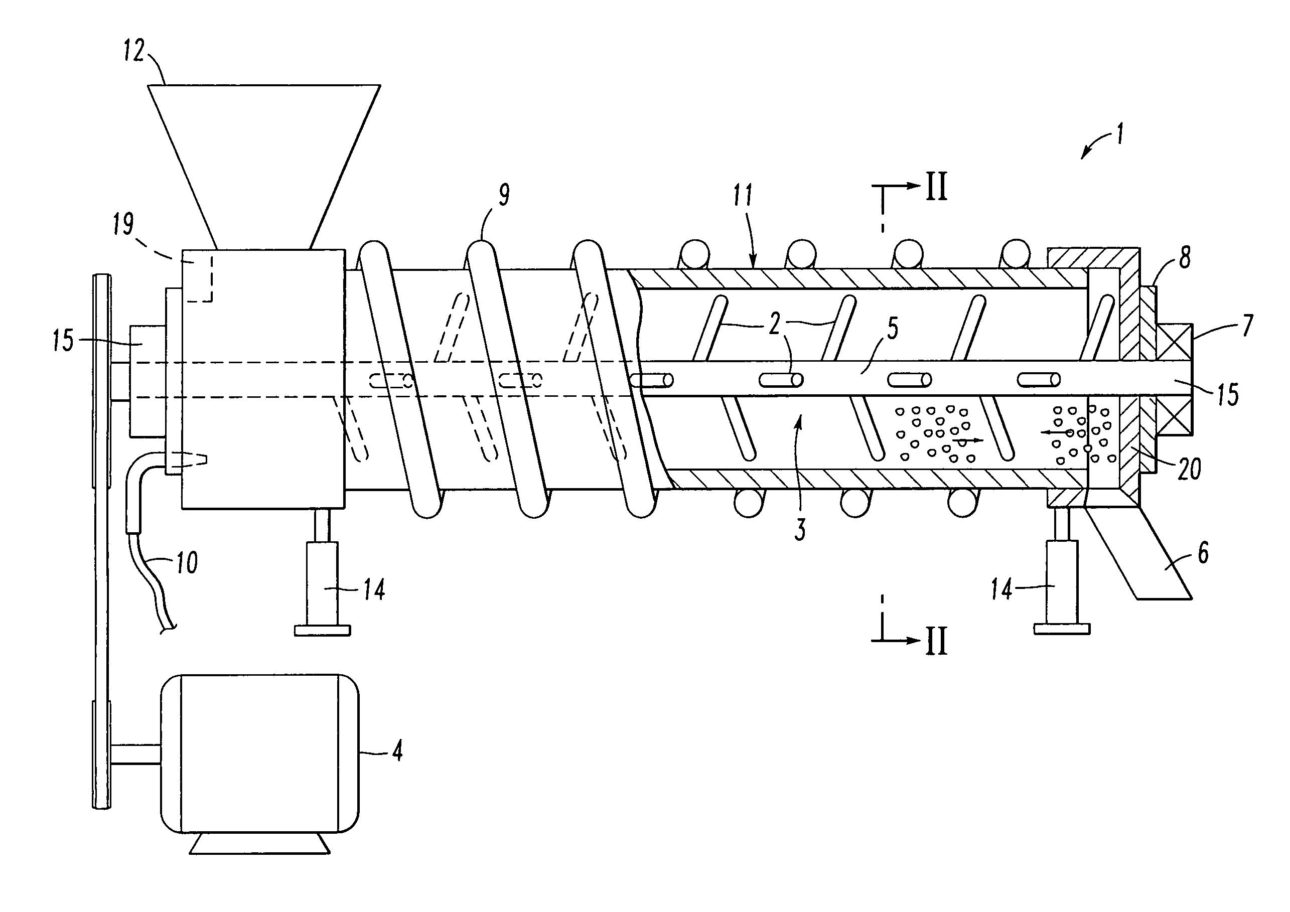
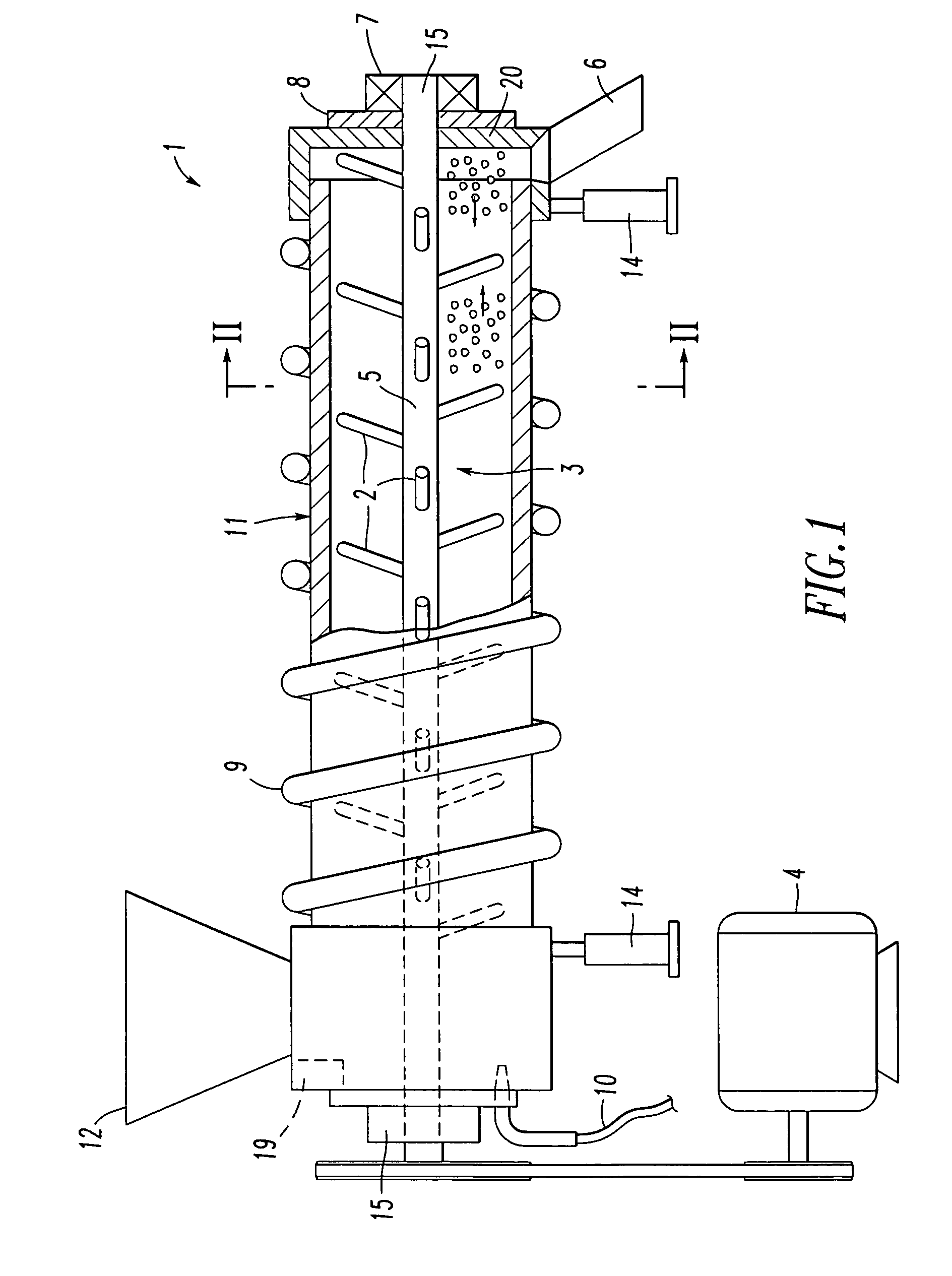
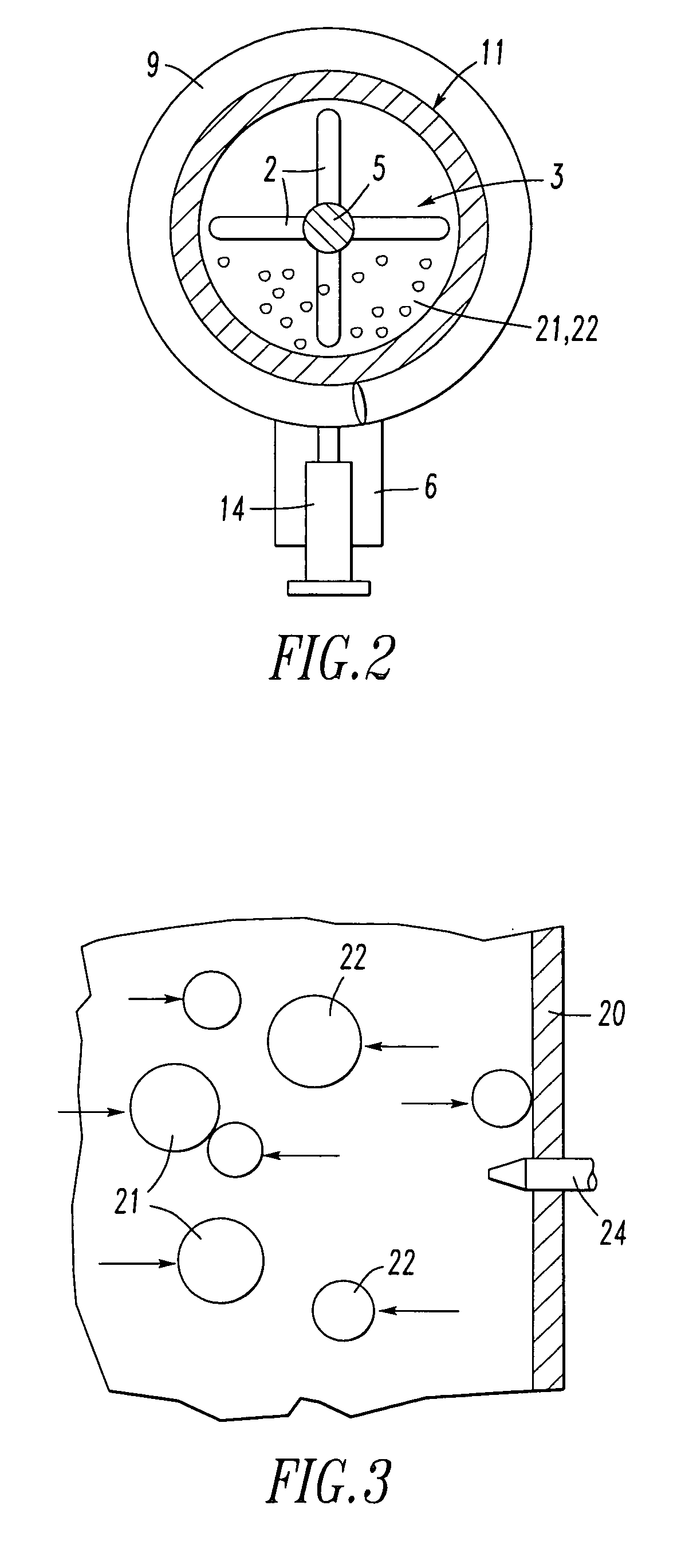
[0022] Referring to FIGS. 1 and 2 we provide a grinder 1 in which a housing 11 surrounds a grinding chamber 3. The grinding chamber 3 is fitted with a center rotating element 5 that has tines, paddles, anvils, blades, hammers or other projections 2 attached for the rotating action necessary for the translation of feed material through the grinding chamber. The chamber preferably has a smooth interior surface with the tines, paddles, blades or hammers traveling over and spaced away from that surface. If desired, baffles or bumps could be provided on this surface. The projections preferably are normal to the exterior surface of the center rotating member. The projections may be arranged in sets with each set in a single plane passing through the center rotating element or in a helix or double helix pattern. The projections may be attached in a manner that they can rotate around a longitudinal axis through the projection or pivot relative to the center rotating element. The center rota...


PUM


Abstract

A method and apparatus to pulverize materials directs solid materials through a generally horizontal chamber. A rotating center element that directs the material along the chamber by basic thrust using projections such as tines, paddles, knives or blades to develop motion and resulting kinetic energy of the material. The material is directed along the axis from the material inlet toward the material outlet and reverses flow at the end of the chamber to recycle back toward the material inlet causing particles of material to collide and fracture. The rotating speed of the center element can be adjusted to affect the grinding rates and particle size distribution. The rotating center element can also be fixtured to optimize material size reduction, differences in material density and the horizontal chamber can be tilted in a declined or inclined plane to affect the grinding rates and size reduction. This method of grinding and pulverizing can accommodate material feed stocks that have as much as 10% moisture since the grinding action creates heat and can drive off the moisture from the material.

Description

FIELD OF INVENTION [0001] The invention relates to a grinding or pulverizing system for reducing material in size. BACKGROUND OF THE INVENTION [0002] Materials have been ground and pulverized historically by either driving the material between two harder surfaces such as the traditional mortar and pestle or by striking material against a hard surface. More recent methods of grinding have taken material and accelerated it with a compressed air source to generate sufficient kinetic energy to fracture the material upon impact with a hard surface. Coffee is ground with the more traditional method of applying a force to the coffee beans between two equally hard surfaces. Vertical shaft grinders today use hammers or comminutors to reduce the particle size of materials. Grinding, or cutting, such as with knives, is yet another subset of grinding with the majority of feed material reduction accomplished via the cutting or cleaving with a hard edge. The term “comminutor” originated with a de...

Claims


Application Information

Patent Timeline
IPC IPC(8): B02C13/00
CPCB02C17/002
Inventor RIENDEAU, ROBERT D.FEDERICO, FRANCIS T.WYNNS, KIM A.
Owner NEW AGE FASTENING SYST
Why Eureka
Try Eureka