Shaft current control brush assembly with drainage
- Summary
- Abstract
- Description
- Claims
- Application Information
AI Technical Summary
Benefits of technology
Problems solved by technology
Method used
Image
Examples
Embodiment Construction
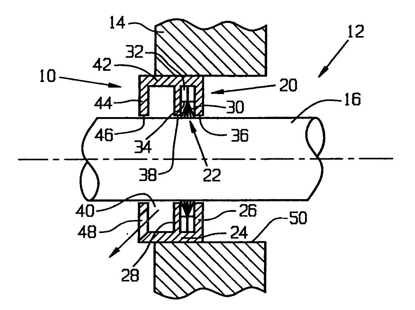
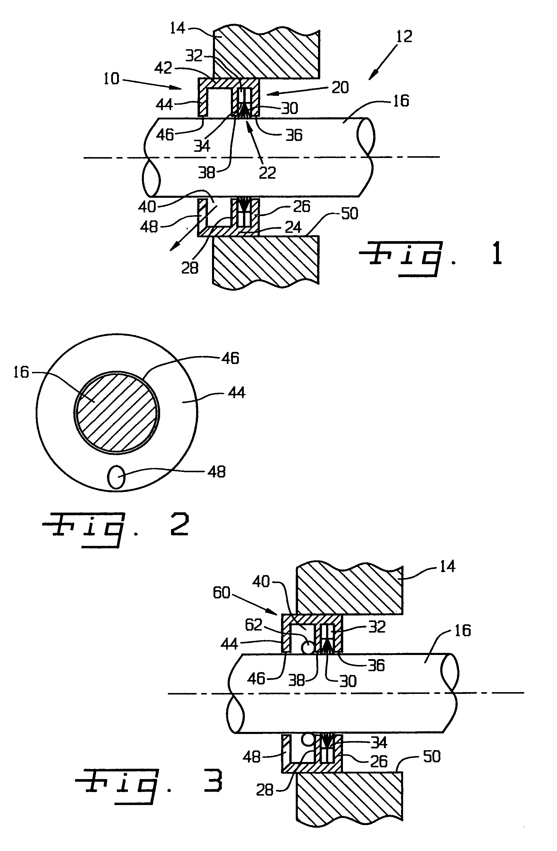
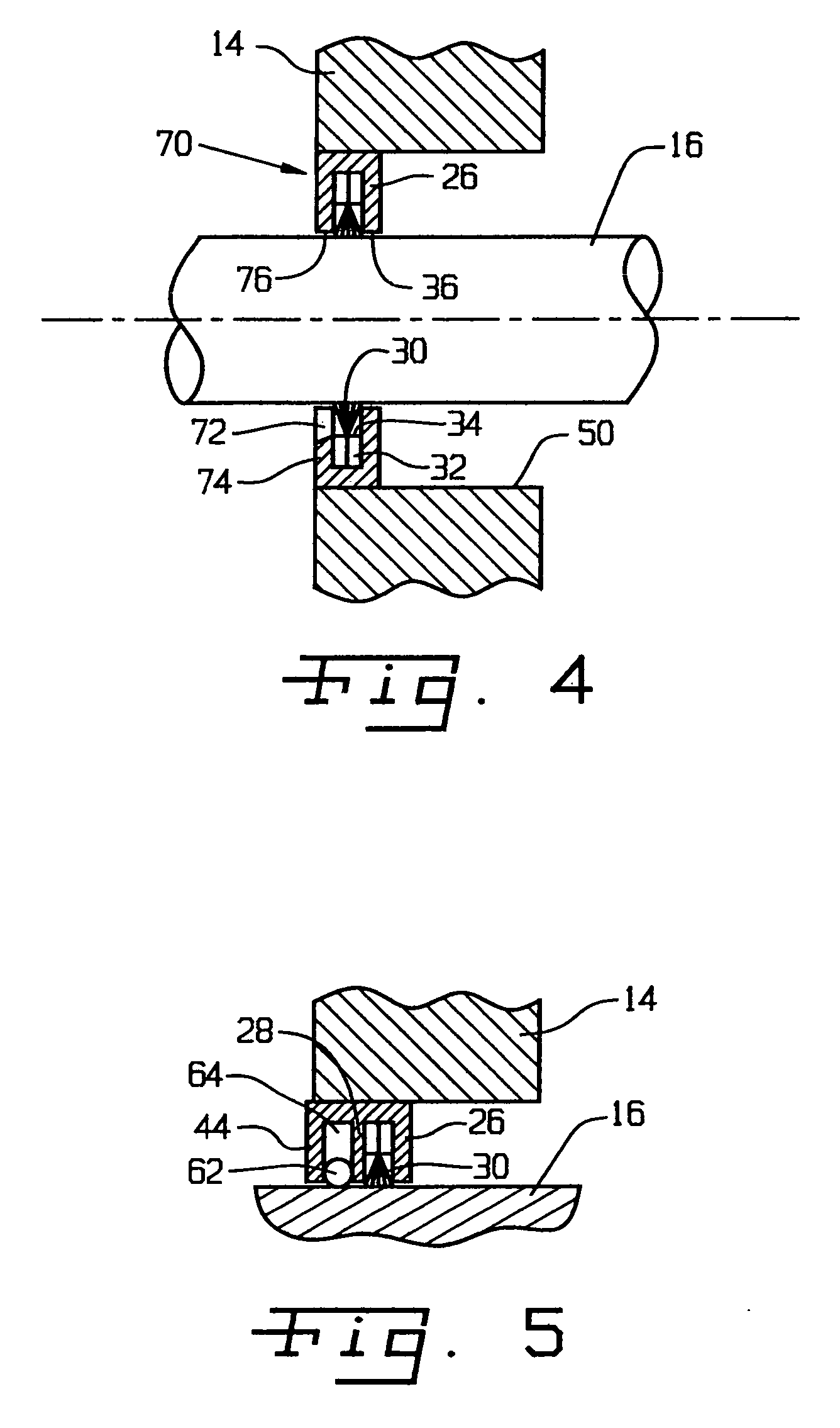
[0024] Referring now more specifically to the drawings and to FIG. 1 in particular, numeral 10 designates a shaft current control brush ring assembly in accordance with the present invention. Brush ring assembly 10 is installed on a motor 12 and specifically in a faceplate 14 of motor 12 for dissipating electrical charges that may build up on a shaft 16 of motor 12. It should be understood that brush ring assembly 10 can be provided in a variety of different sizes for use in motors of different types and on shafts 16 of different diameters.
[0025] Brush ring assembly 10 is of generally annular shape, encircling shaft 16. Brush ring assembly 10 is secured to faceplate 14 and is operatively arranged between shaft 16 and faceplate 14 to dissipate static or other charges that build on motor shaft 16 during operation of motor 12.
[0026] Brush ring assembly 10 includes an annular channel 20 and a brush assembly 22 disposed therein. Channel 20 includes a cylindrical outer band 24 with an i...
PUM
 Abstract
Description
Claims
Application Information
 - R&D
- Intellectual Property
- Life Sciences
- Materials
- Tech Scout
- Unparalleled Data Quality
- Higher Quality Content
- 60% Fewer Hallucinations
Browse by: Latest US Patents, China's latest patents, Technical Efficacy Thesaurus, Application Domain, Technology Topic, Popular Technical Reports.
© 2025 PatSnap. All rights reserved.Legal|Privacy policy|Modern Slavery Act Transparency Statement|Sitemap|About US| Contact US: help@patsnap.com


