Wireless terminals

a terminal and wireless technology, applied in the field of wireless terminals, can solve the problems of physical largeness of the antenna and difficulty in using over more than two cellular bands, and achieve the effect of reducing the fractional bandwidth of the antenna and low sar performan

Inactive Publication Date: 2007-02-22
BREAKWATERS INNOVATIONS
View PDF23 Cites 38 Cited by
  • Summary
  • Abstract
  • Description
  • Claims
  • Application Information

AI Technical Summary

Benefits of technology

[0008] The present invention is based on the realisation that the low SAR performance favours the use of a PIFA predominantly for transmission and a co-located notch can be used for reception (or in those applications ...

Problems solved by technology

However, such antennas are physically large and ...

Method used


Image

  • Wireless terminals
  • Wireless terminals
  • Wireless terminals

Examples


Embodiment Construction

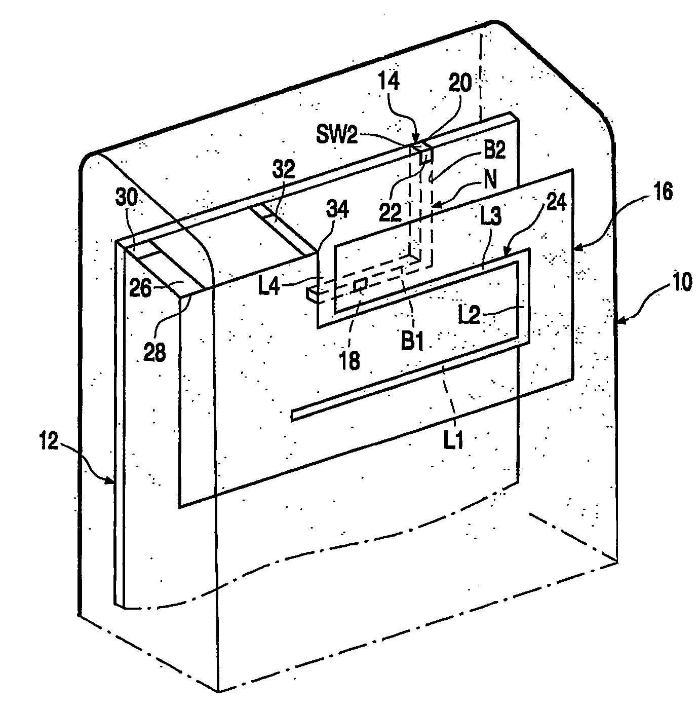
[0018]FIG. 1 shows the European and North American cellular bands. The transmit bands Tx are shown in dark grey (to the left of each pair), while the receive bands Rx are shown in light grey (to the right). In Europe both the GSM and DCS bands, 880 to 960 MHz and 1710 to 1880 MHz, respectively, accommodate time division duplex systems, while the UMTS bands, 1920 to 1980 MHz (transmit) and 2110 to 2170 MHz (receive), are predominantly frequency division, full duplex. In the USA, a mix of systems and duplex methods are used in the AMPS and PCS bands, 824 to 894 MHz and 1850 to 1990 MHz, respectively. The advanced wireless systems (AWS) bands, 1710 to 1755 MHz and 2110 to 2155 MHz, have recently been allocated for 3G systems, though it has yet to be resolved how the bands will be used.

[0019] Currently many phones are being made to support the European GSM and DCS bands together with the US PCS bands (in the TDMA IS54 / 136 mode). Since many other countries have adopted either the Europe...


PUM


Abstract

A wireless terminal includes a housing (10) containing a substrate (12) having a ground plane, RF components mounted on the substrate, a PIFA (Planar Inverted-F Antenna) (16) carried by the substrate and coupled electrically to the RF components for transmitting and receiving signals and a notch antenna (14) in the substrate for receiving signals in a frequency band at least partially overlapping the transmission bandwidth of some of the signals transmitted by the PIFA. The notch antenna is de-activated when the PIFA (16) is being used for transmitting a signal lying within the said transmission bandwidth.

Description

TECHNICAL FIELD [0001] The present invention relates to improvements in or relating to wireless terminals. The invention has particular, but not exclusive, application to multiple standard cellular telephones operable in accordance telephone standards such as GSM (880 to 960 MHz), DCS (1710 to 1880 MHz) and PCS (1850 to 1990 MHz) and optionally Bluetooth® (ISM band in the region of 2.4 GHz). The present invention also relates to a wireless module having an antenna and at least those components included in the coupling stages. BACKGROUND ART [0002] In the course of developing successive generations of cellular telephones a great deal of effort has been spent on reducing the volume of the wireless terminal. Coupled with this reduction in the overall volume has been the desire to reduce the volume of the antenna whilst still maintaining its sensitivity. Externally mounted monopole antennas have been succeeded by internal antennas such as PIFAs (Planar Inverted-F Antennas) and notch ant...

Claims


Application Information

Patent Timeline
IPC IPC(8): H01Q1/24H01Q1/52H01Q9/04H01Q13/10H01Q21/28H01Q21/30
CPCH01Q1/242H01Q1/521H01Q9/0421H01Q13/106H01Q21/28H01Q21/30H01Q1/243
Inventor BOYLE, KEVIN R.
Owner BREAKWATERS INNOVATIONS
Why Eureka
Try Eureka