Method for fabricating a micro-lens mold and a concave micro-lens

a technology of concave micro-lens and molds, which is applied in the field of micro-lens manufacturing, can solve the problems of inability to produce compact array structures, reduced numerical apertures, and relatively poor mechanical properties of materials

Inactive Publication Date: 2007-02-22
NAT CHUNG SHAN INST SCI & TECH
View PDF1 Cites 9 Cited by
  • Summary
  • Abstract
  • Description
  • Claims
  • Application Information

AI Technical Summary

Benefits of technology

[0016] Detailed characteristics and advantages of the invention will be illustrated in detail in the detailed description below, and the content is sufficient for those skilled in the art to understand and utilize the technology content of t

Problems solved by technology

The disadvantage of this process is that it is necessary to use a thermoplastic polymer material, and the film made from this kind of material is typically thin, i.e., it is difficult to produce a lens with high curvature, and the mechanical properties of the material are relatively poor.
However, the disadvantage of this kind of lens is that a micro-lens with a large curvature cannot be formed, so that the numerical aperture will be diminished, and a very compact array structure cannot be produced due to the width of the mold itself.
Also, according to this method it

Method used


Image

  • Method for fabricating a micro-lens mold and a concave micro-lens
  • Method for fabricating a micro-lens mold and a concave micro-lens
  • Method for fabricating a micro-lens mold and a concave micro-lens

Examples


Embodiment Construction

[0027] In order to illustrate the purposes, constructions, characteristics and functions of the invention, it will be described in detail below with reference to the embodiments. The abovementioned content of the invention and the detailed description below are intended to exemplify and explain the principle of the present invention, and also to provide a further explanation about the claims of the invention.

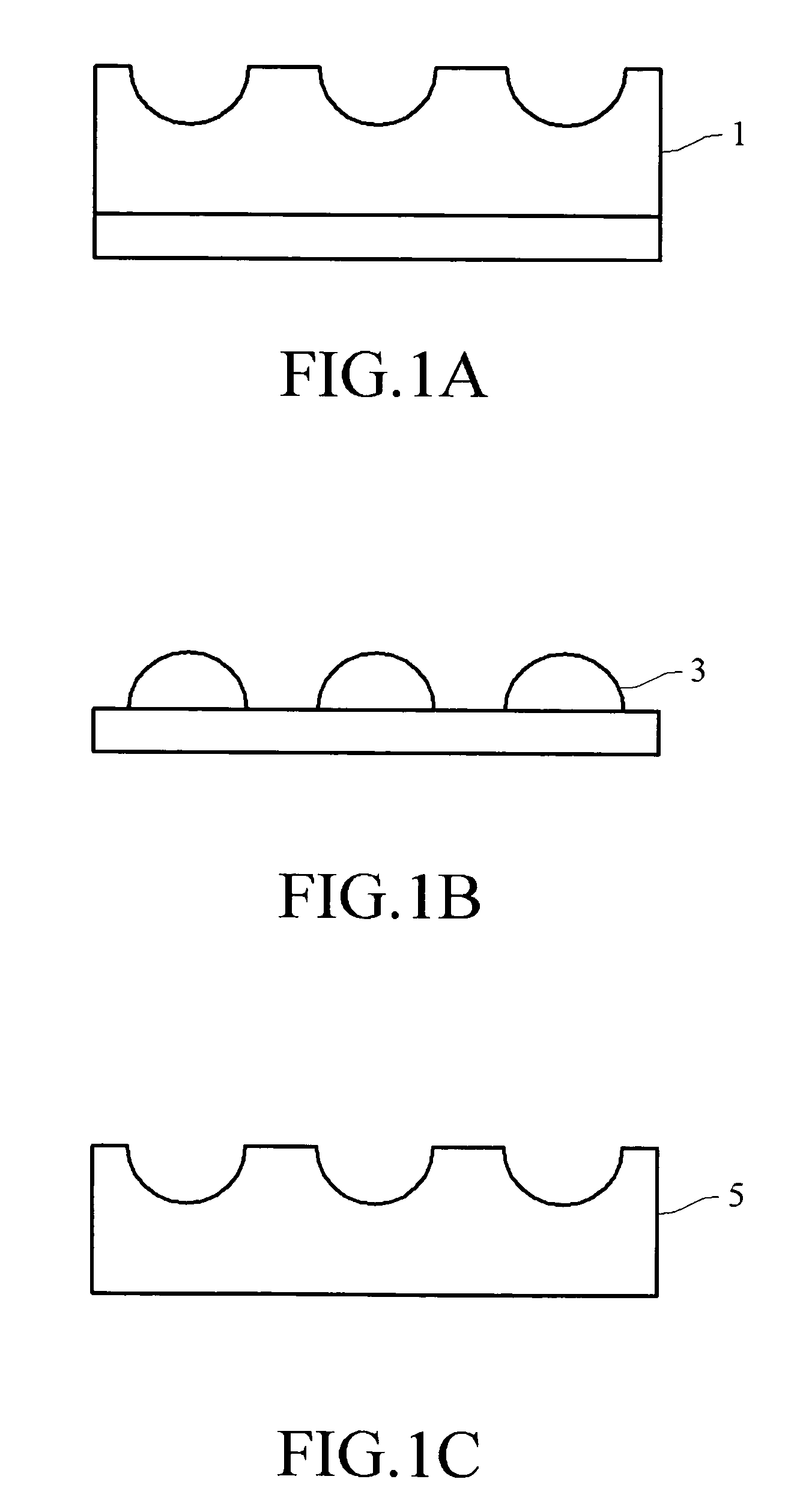
[0028] The object of the present invention is to simplify the conventional process for mass-producing micro-lens molds and micro-lenses, and to develop a new process for producing a micro-lens mold. A LIGA-like process for a thick film (photo resist) can be used along with the application of a UV-curing glue to directly produce a concave micro-mold 1 as shown in FIG. 1A, and mold a convex micro-lens (micro-lens array) product 3 as shown in FIG. 1B. Furthermore, since the concave micro-mold structure employs a material with suitable optical properties, if it can be released from...


PUM


Abstract

A method for fabricating a micro-lens mold comprises forming a thick film on a substrate, patterning the thick film to form a micro-capillary, filling the micro-capillary with a heat curing glue liquor, rotating the substrate so that the liquid in the micro-capillary presents a circular arc shape as a micro-lens because of the surface tension of the material itself and the adhesion of the micro-capillary, and curing and shaping the heat curing glue liquor by the irradiation of a light source or by heating.

Description

BACKGROUND OF THE INVENTION [0001] 1. Field of Invention [0002] The present invention relates to a method for fabricating micro-lens, and particularly to a method for fabricating micro-lens mold and concave micro-lens. [0003] 2. Related Art [0004] In the development of photoelectric products, since the micro-optical lens can produce an optical effect in a small area, it has become a basic element greatly demanded in this industry. For example, an array of optical lenses is used in the backlight plate of a Liquid Crystal Display (LCD) to produce a uniform backlight. Moreover, the improving of photoelectric semiconductor elements, such as laser diodes, light emitting diodes, photo-detectors, a single element is substituted by an array, while its increasing application field, such as an optical computing and optical communication system, greatly needs the use of the micro-lens array. Therefore, those skilled in the art, such as manufacturers and academics, are chasing to develop the te...

Claims


Application Information

Patent Timeline
IPC IPC(8): G02B27/10
CPCG02B3/0031G02B3/0056
Inventor WU, JEN-CHINYANG, HSI-HARNGCHANG, CHIA-HUACHIAN, CHI-HAW
Owner NAT CHUNG SHAN INST SCI & TECH
Why Eureka
Try Eureka