

Optical element and lighting device provided therewith
- Summary
- Abstract
- Description
- Claims
- Application Information
AI Technical Summary
Benefits of technology
Problems solved by technology
Method used
Image

Examples
first embodiment
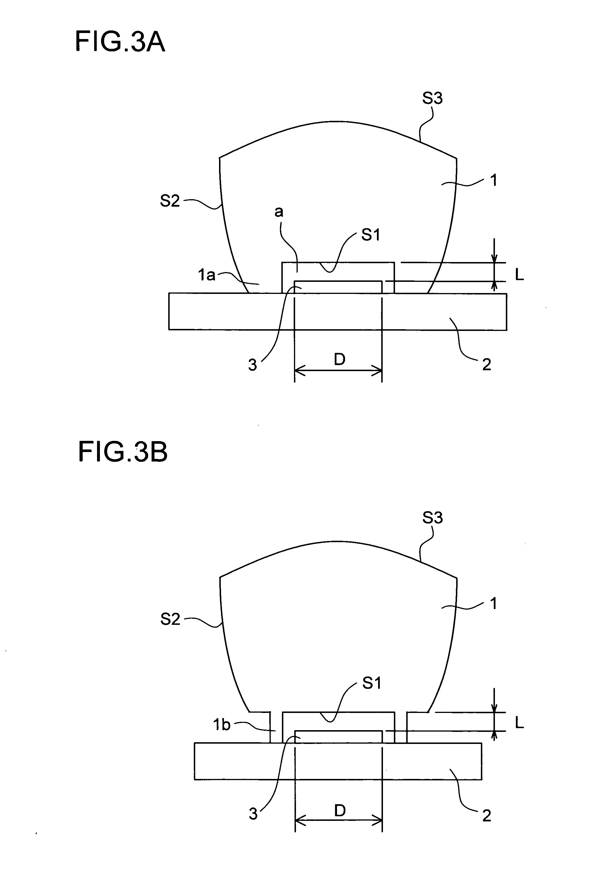
[0083] Hereinafter, one embodiment of the present invention will be described with reference to the accompanying drawings. The invention refers to an optical element which condenses in a predetermined direction light emitted from a light source having a widening surface form. This optical element has a first surface, a second surface, and a third surface. The first surface is an entrance surface formed of a flat surface where light emitted from the light source enters. The third surface is an exit surface from which light entering via the first surface exits and which is so formed as to be convexed on the light exit side. The second surface is a reflection surface which directs, to the third surface by total reflection, part of light entering via the first surface and which is so formed as to be convexed on the light entrance side. With the first surface disposed near the light source, light exiting from the light source enters the first surface, is totally reflected by the convexed...
example 1
[0151]
Material: PMMARefractive index (d-line): 1.4914νd: 57.82[Effective[Z (mm)][CR (mm)][k]diameter (mm)]Light source (3)0INF0.0010First surface (S1)0.03INF0.0010Second surface (S2)−3.0954−1.0030surface apexThird surface (S3)29.03−500.0030surface apex
example 2
[0152]
Material: PolycarbonateRefractive index (d-line): 1.5834νd: 30.23[Effective[Z (mm)][CR (mm)][k]diameter (mm)]Light source (3)0INF0.0010First surface (S1)0.5INF0.0010Second surface (S2)−2.6254−1.0030surface apexThird surface (S3)29.5−400.0030surface apex
PUM
 Abstract
Description
Claims
Application Information