
Apparatus for the multiplication of air flow in internal combustion engines increasing horsepower and torque, while reducing emissions

a multi-purpose, internal combustion engine technology, applied in the field of motor vehicles, can solve the problems of complex design, increased under-hood temperature and often higher intake air temperature, and loss of original engine torque, and achieve the effect of effectively and reliably increasing the total volume of air supplied, effectively reducing the emission level of diesel engines, and increasing horsepower and torque in internal combustion engines

Inactive Publication Date: 2007-03-01
GREEN CARL ANSON
View PDF8 Cites 17 Cited by
  • Summary
  • Abstract
  • Description
  • Claims
  • Application Information

AI Technical Summary

Benefits of technology

"The invention provides an apparatus that can increase air flow to an internal combustion engine without using moving parts, which can wear out over time and increase costs. The apparatus can also increase the amount of air flow for a lower cost per unit and with less installation time. It can also increase air flow without causing malfunctions or requiring high warranty or replacement costs. The apparatus can be mounted in different locations and can introduce alternative fuels or gases into the engine. Additionally, it can reduce emissions levels in diesel engines."

Problems solved by technology

There are many improvements that will be accomplished through this new technology that are significant problems in previous technologies.
This results in higher under-hood temperatures and often higher intake air temperatures.
In both prior technologies the driving mechanisms result in losses from the original engine torque that need to be overcome prior to net increases in output.
Both prior technologies have complex designs that contain many moving parts, wearing surfaces, complicated manufacturing processes, and high warranty or maintenance costs related.
This lag scenario is the leading cause of low rpm or idle-mode emission problems with current diesel engine operation.

Method used


Image

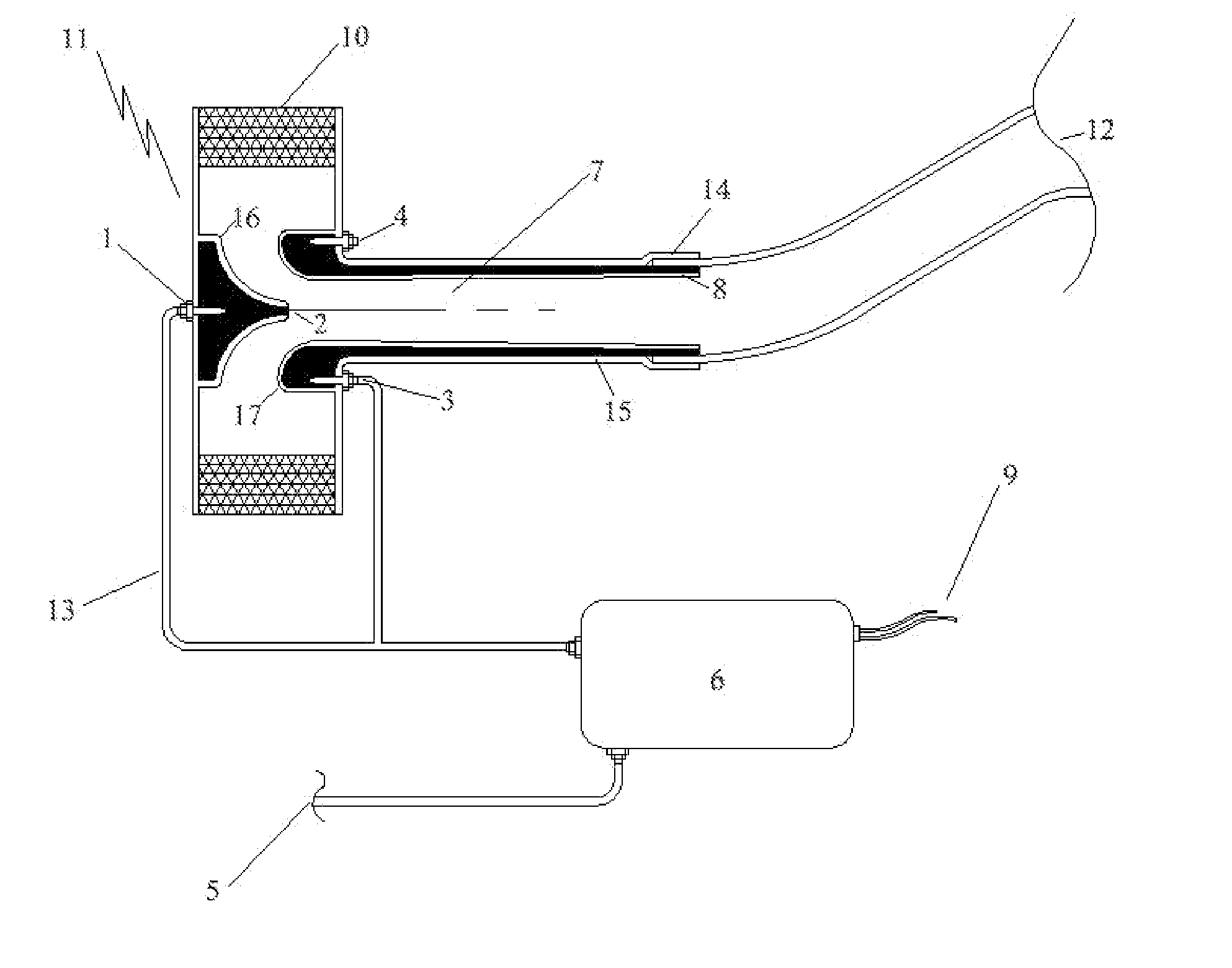
  • Apparatus for the multiplication of air flow in internal combustion engines increasing horsepower and torque, while reducing emissions
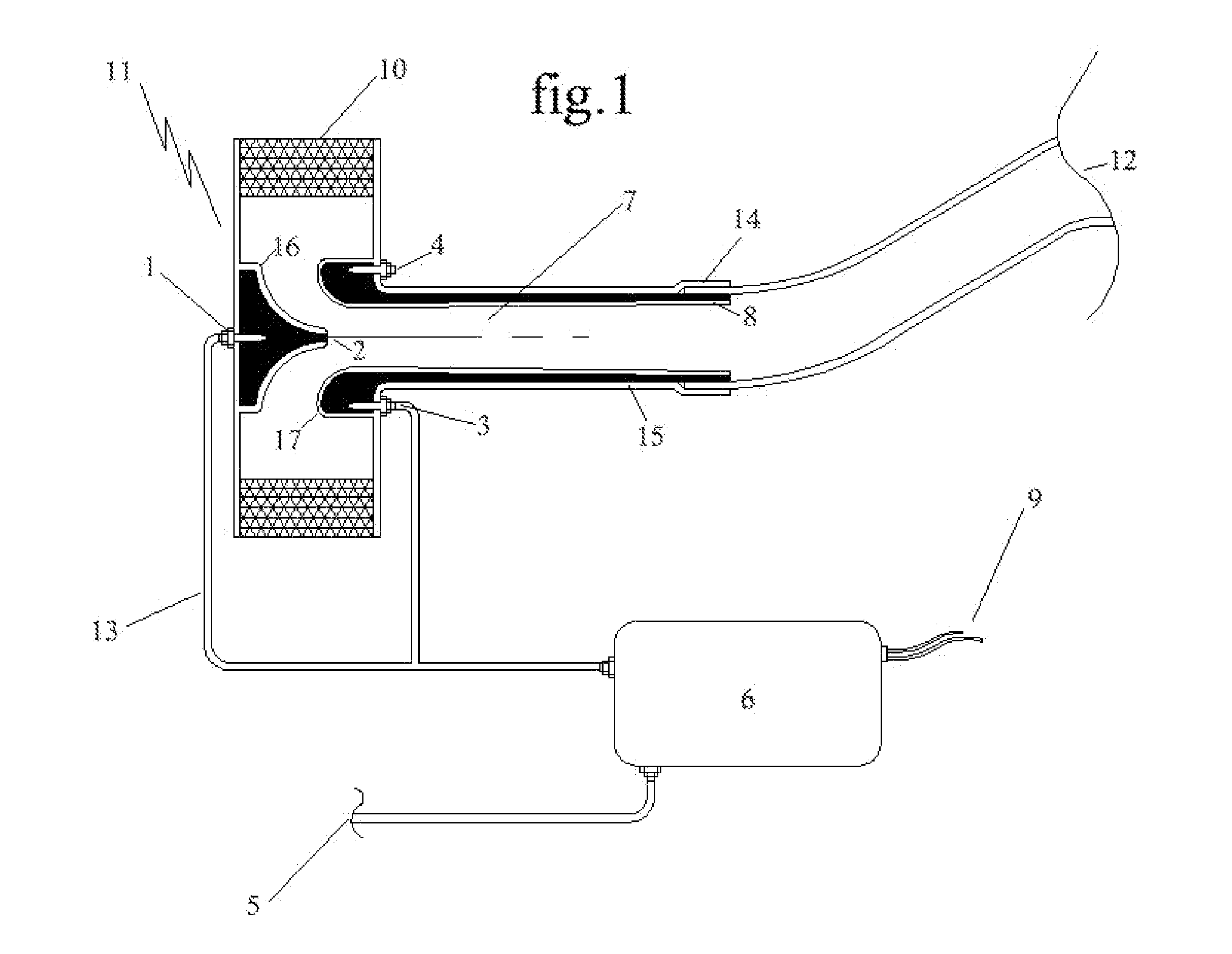
  • Apparatus for the multiplication of air flow in internal combustion engines increasing horsepower and torque, while reducing emissions
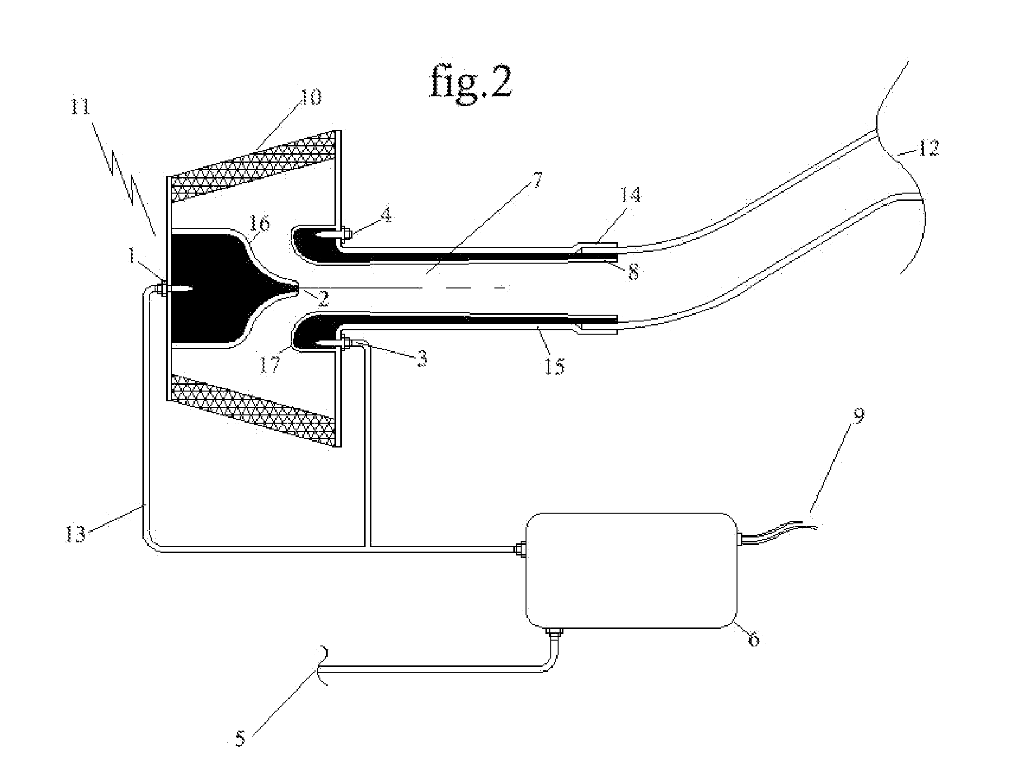
  • Apparatus for the multiplication of air flow in internal combustion engines increasing horsepower and torque, while reducing emissions

Examples


Embodiment Construction

[0014] Detailed descriptions of the preferred embodiment are provided herein. It is to be understood, however, that the present invention may be embodied in various forms. Therefore, specific details disclosed herein are not to be interpreted as limiting, but rather as a basis for the claims and as a representative basis for teaching one skilled in the art to employ the present invention in virtually any appropriately detailed system, structure or manner. The invention having:

(1) a nozzle for calibrating and dispensing compressed air that is unique in geometric shape;

(2) a housing chamber to introduce compressed air through a vortex nozzle passage that is unique in geometric shape;

(3) a tube for transporting alternative fuel or gases that is current fuel / gas delivery plumbing technology;

(4) a nozzle for calibrating alternative fuel or gases that is unique in geometric shape

(5) a source or reservoir to hold / supply compressed air that is current reservoir technology;

(6) a ...


PUM


Abstract

Compressed air is fed from a pressurized reservoir (5) thru a nozzle / vortex unit (1) simultaneously drawing ambient air through an air filter element (10). The air mixes in a merging plenum (7) where air-charge multiplication occurs resulting in boost or positive pressure conditions. The positive pressure introduced to the intake air of the engine results in a higher cylinder combustion compression ratio. The increase compression ratio with proper air to fuel ratio results in an increase in horsepower and torque. Air is controlled by a computer (6), regulators, solenoids, micro-switches, and nozzle configurations. Air is supplied via reservoir (5) and replenished from mechanical or electric air pumps (FIG. 3 18s, 18b, 18c, 18d). Alternative fuels / gases can be added such as nitrous oxide or propane (3, 4). In diesel engine applications (FIG. 3), the power and torque increases can also be experienced, but also reduce emission levels at low rpm or idle mode conditions.

Description

CROSS REFERENCE TO RELATED APPLICATIONS [0001] This application claims the benefit of Provisional Application No. 60 / 594,218, filed on Mar. 20, 2005.BACKGROUND OF THE INVENTION [0002] This invention relates generally to the field of motor vehicles and more specifically to an apparatus for the multiplication of air flow in internal combustion engines increasing horsepower and torque, while reducing emissions. [0003] The use of increasing intake air on internal combustion engines has been identified to be a very effective way to improve combustion burn rates and efficiencies. Raising the intake air-charge to a “boost” or positive pressure condition is the most effective and dependable way to result in horsepower and torque gains that are not typical to naturally aspirated engines. [0004] Previous technologies have been able to “boost” or positive pressure through complex apparatuses. Turbo-charging requires to be driven from exhaust gas pressures, and super-charging requires to be dri...

Claims


Application Information

Patent Timeline
Patent Type & Authority Applications(United States)
IPC IPC(8): F02B23/00F02M35/02
CPCF02B21/00F02B29/00F02B33/34F02B39/04F02M35/024F02M35/10019F02M35/10222Y02T10/146Y02T10/14Y02T10/12
Inventor GREEN, CARL ANSON
Owner GREEN CARL ANSON
Learn More