Plasma processing apparatus and processing method, and flat panel display manufacturing method

a technology of plasma processing apparatus and manufacturing method, which is applied in the direction of welding apparatus, manufacturing tools, electric discharge tubes, etc., can solve the problems of increasing and achieve the effect of suppressing the increase in the manufacturing cost of plasma processing apparatus

Inactive Publication Date: 2007-03-01
GOTO NAOSHISA +2
View PDF5 Cites 9 Cited by
  • Summary
  • Abstract
  • Description
  • Claims
  • Application Information

AI Technical Summary

Benefits of technology

[0011] The present invention has been made to solve this problem, and has as its object to suppress an increase ...

Problems solved by technology

This increases the manufacturing ...

Method used


Image

  • Plasma processing apparatus and processing method, and flat panel display manufacturing method
  • Plasma processing apparatus and processing method, and flat panel display manufacturing method
  • Plasma processing apparatus and processing method, and flat panel display manufacturing method

Examples


first embodiment

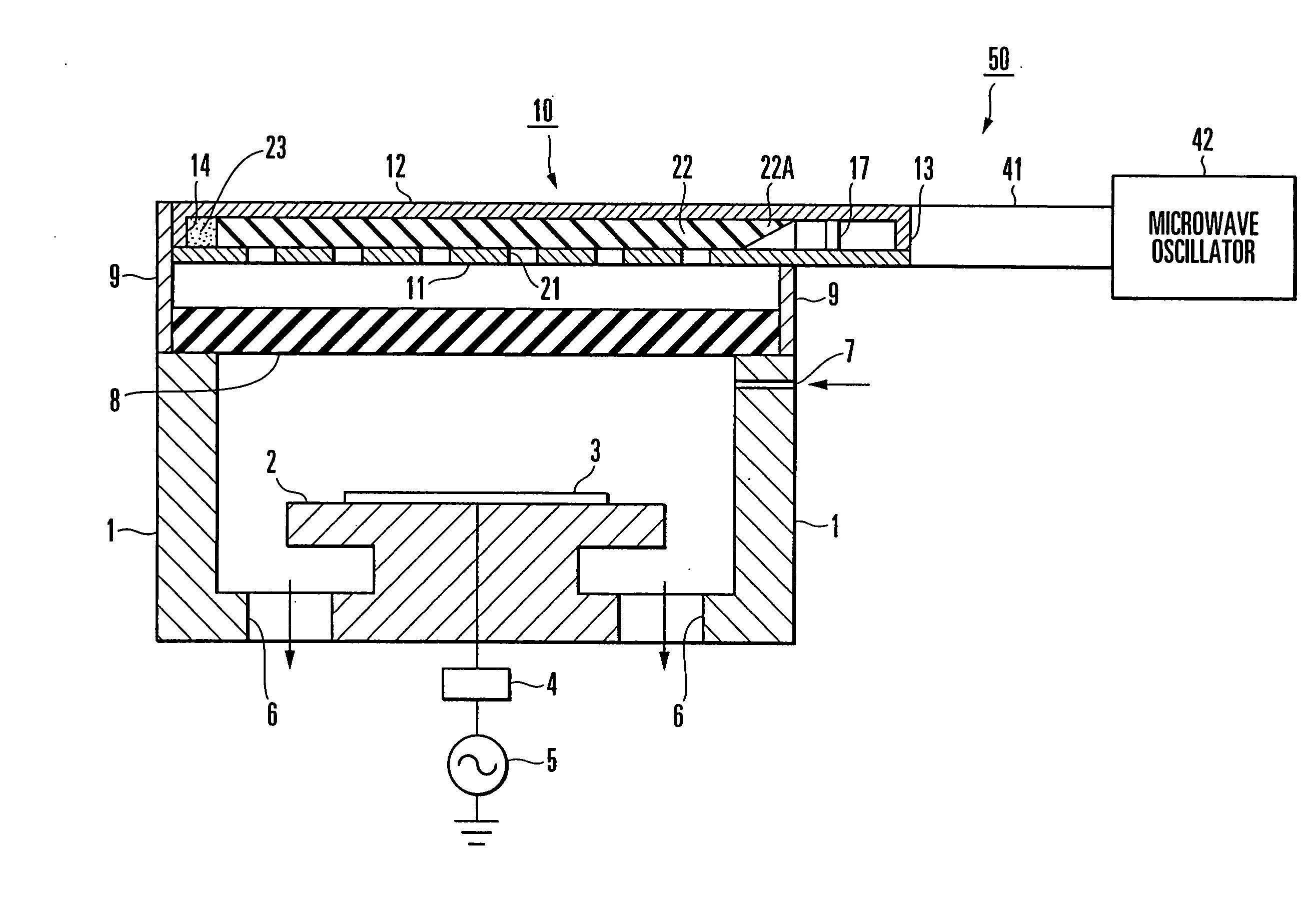
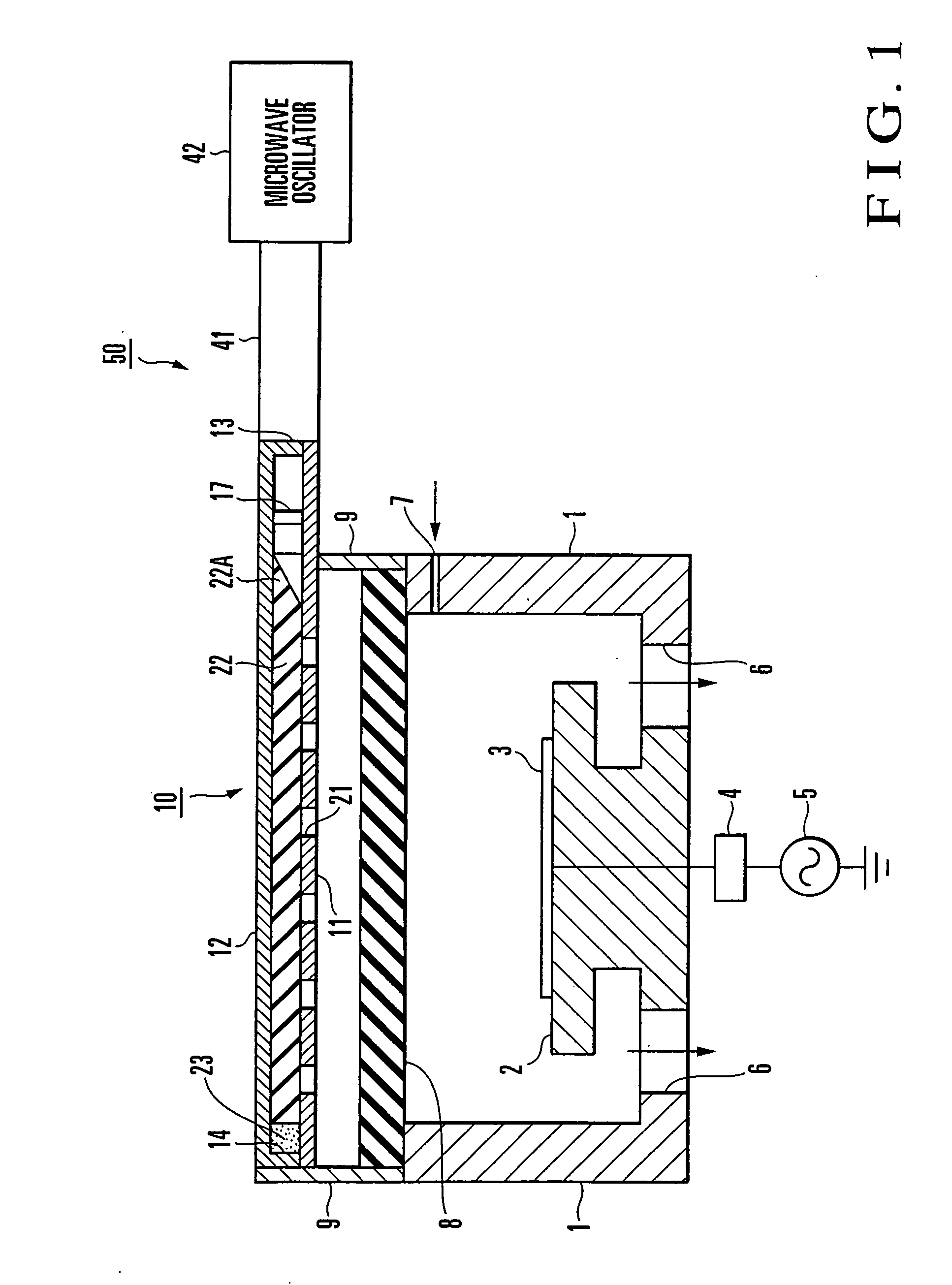
[0028] As shown in FIG. 1, a plasma processing apparatus according to the first embodiment of the present invention has a bottomed cylindrical processing vessel 1 which is square when seen from the top. The processing vessel 1 is made of a metal such as Al. A stage 2 is disposed at the central portion of the bottom surface of the processing vessel 1. An LCD substrate 3 or the like is arranged as a target object on the upper surface of the stage 2. The stage 2 is connected to a high-frequency power supply 5 through a matching box 4.

[0029] Exhaust ports 6 for vacuum evacuation are formed in the peripheral portion of the bottom surface of the processing vessel 1. A gas introduction port 7 through which a gas is introduced is formed in the side wall of the processing vessel 1. When the plasma processing apparatus is to be used as an etching apparatus, a plasma gas such as Ar and a reaction gas such as CF4 are introduced.

[0030] The upper opening of the processing vessel 1 is closed wit...

second embodiment

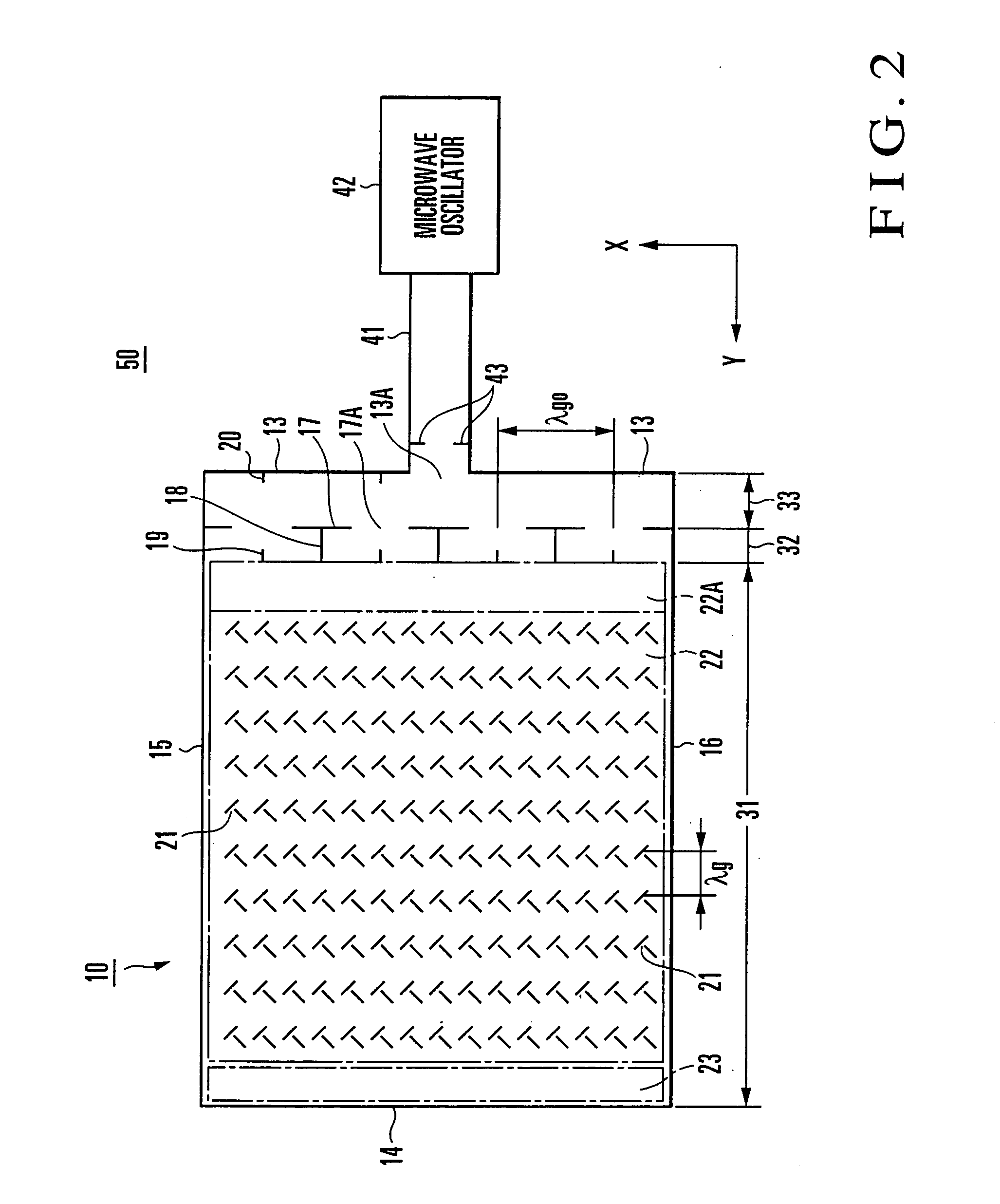
[0065] A plasma processing apparatus according to the second embodiment of the present invention uses a microwave supply device in which the microwave supply power has a distribution within a surface where the slots of a parallel-plate antenna are formed. This microwave supply device will be described with reference to FIG. 6. In FIG. 6, the constituent elements which correspond to those shown in FIG. 2 are denoted by the same reference numerals as in FIG. 2.

[0066] In a microwave supply device 250 shown in FIG. 6, the interior of a parallel-plate waveguide 231A of a parallel-plate antenna 231 is divided into three regions A, B, and C by two partition members 218. The width (length in the X-axis direction) of each of the regions A to C is N times (N is an integer larger than 2) the width of each of square waveguides 32A to 32H. In this embodiment, N=4.

[0067] The partition members 218 are connected to E-surfaces 18 of a square waveguide which are perpendicular to first and second co...

third embodiment

[0076] A plasma processing apparatus according to the third embodiment of the present invention uses a plurality of microwave supply devices in combination. This plasma processing apparatus will be described with reference to FIGS. 8 and 9. In FIGS. 8 and 9, the constituent elements corresponding to those shown in FIG. 2 or 6 are denoted by the same reference numerals as in FIG. 2 or 6.

[0077] The arrangement shown in FIG. 8 uses two microwave supply devices 350A and 350B respectively having parallel-plate antennas 310A and 310B. In each of the parallel-plate antennas 310A and 310B, the interior of a parallel-plate waveguide 231A is divided into a plurality of regions by partition members 218, in the same manner as in the microwave supply device 250 shown in FIG. 6. The two microwave supply devices 350A and 350B are arranged such that side walls 14 as the terminal ends of the respective parallel-plate waveguides 231A oppose, so respective first conductive plates 11A of the parallel-...


PUM

PropertyMeasurementUnit
Dielectric polarization enthalpyaaaaaaaaaa
Poweraaaaaaaaaa
Shapeaaaaaaaaaa

Abstract

A plasma processing apparatus includes a stage, processing vessel, and microwave supply device. A target object is placed on the stage. The processing vessel accommodates the stage. The microwave supply device supplies microwaves into the processing vessel, and includes a parallel-plate waveguide, a plurality of slots, a square waveguide array, and a distributor. The parallel-plate waveguide includes a first conductive plate which is rectangular when seen from the top and arranged to oppose the stage, and a second conductive plate which is arranged substantially parallel to the first conductive plate and has the same shape as that of the first conductive plate when seen from the top. The plurality of slots are formed in the first conductive plate. The square waveguide array includes a plurality of square waveguides aligned in their widthwise directions (X) perpendicular to there axial directions (Y). One end of each of the square waveguides is connected to the parallel-plate waveguide. The distributor is connected to the other end of each of the square waveguides and distributes and supplies the microwaves to the square waveguides with the same phase. A plasma processing method and a flat panel display manufacturing method are also disclosed.

Description

BACKGROUND OF THE INVENTION [0001] The present invention relates to a plasma processing apparatus and processing method and, more particularly, to a plasma processing apparatus and processing method for processing a target object such as a flat panel display using a plasma generated by microwaves. [0002] In the manufacture of a flat panel display such as an LCD (liquid crystal display), plasma processing apparatuses are widely used to perform processes such as etching, ashing, and CVD (Chemical Vapor Deposition). Among the plasma processing apparatuses, a microwave plasma processing apparatus is available which supplies microwaves into a processing vessel to ionize or excite a gas in the processing vessel, thus generating a plasma. As the microwave plasma processing apparatus, one which uses a plane antenna, e.g., a radial line slot antenna, having a circular radiation surface as a microwave supply means has been put into practical use. Currently, a microwave plasma processing appar...

Claims


Application Information

Patent Timeline
IPC IPC(8): B23K9/00B23K9/02
CPCH01J37/32229H01J37/32192
Inventor GOTO, NAOHISAOHMI, TADAHIROMORIMOTO, TAMOTSU
Owner GOTO NAOSHISA
Why Eureka
Try Eureka