[0008] The present invention solves these problems, as well as others, by providing a warming unit and system for warming a patient infusion medium, wherein the warming unit includes an ergonomic design that is comfortably securable to a patient or easily attachable to another location, and provides an efficient warming operation, a low risk of leakage, and an improved flowrate over the medium warmers of the prior art. Embodiments of the present invention include separate
control electronics from the warming unit, thereby reducing or eliminating problems associated with prior art
integrated systems.
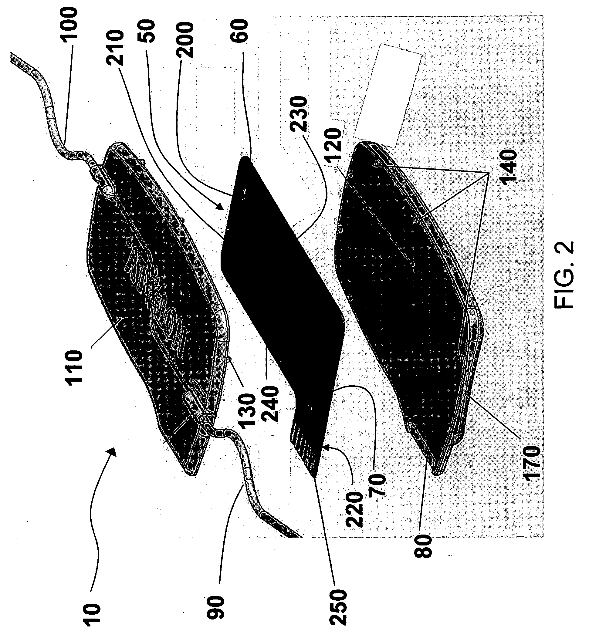
[0009] According to one embodiment of the present invention, the warming unit includes an outer casing, a laminated heating
assembly, one or more sensors, and inlet and outlet tubes. The warming unit optionally includes a connector port for connecting the
fluid warmer to a controller, which controls various functions of the
fluid warmer. A fluid conduit is formed within the casing, and, according to one embodiment, the fluid conduit defines a serpentine or meandering path, prolonging a time period during which a medium passing through the warming unit is in contact with, or in close proximity to, the laminated heating
assembly. Among other advantages, the conduit of some embodiments of the present invention reduces formation of air bubbles in the medium to be conducted, by
sizing and / or shaping the cross-sectional area of the conduit such that bubble formation has a low likelihood of occurrence.
[0011] The laminated heating
assembly is provided within the outer casing, for example, by being enclosed between first and second portions of the outer casing. Further, the warming unit optionally includes a plurality of extensions and corresponding openings formed on the first and second casing portions, respectively, to align and secure the casing portions together. The warming unit optionally also includes a seal disposed between the first and second casing portions. The seal is seated, for example, within a groove formed in one of the first and second casing portions. The first and second casing portions may be secured together by
ultrasonic welding, gluing, or any other suitable method of attachment. In some embodiments, once assembled together, the first and second casing portions are permanently secured to each other. As a result, the warming unit has improved leakage and
tamper resistance. In some variations, the warming unit is intended to be disposed after a
single use.
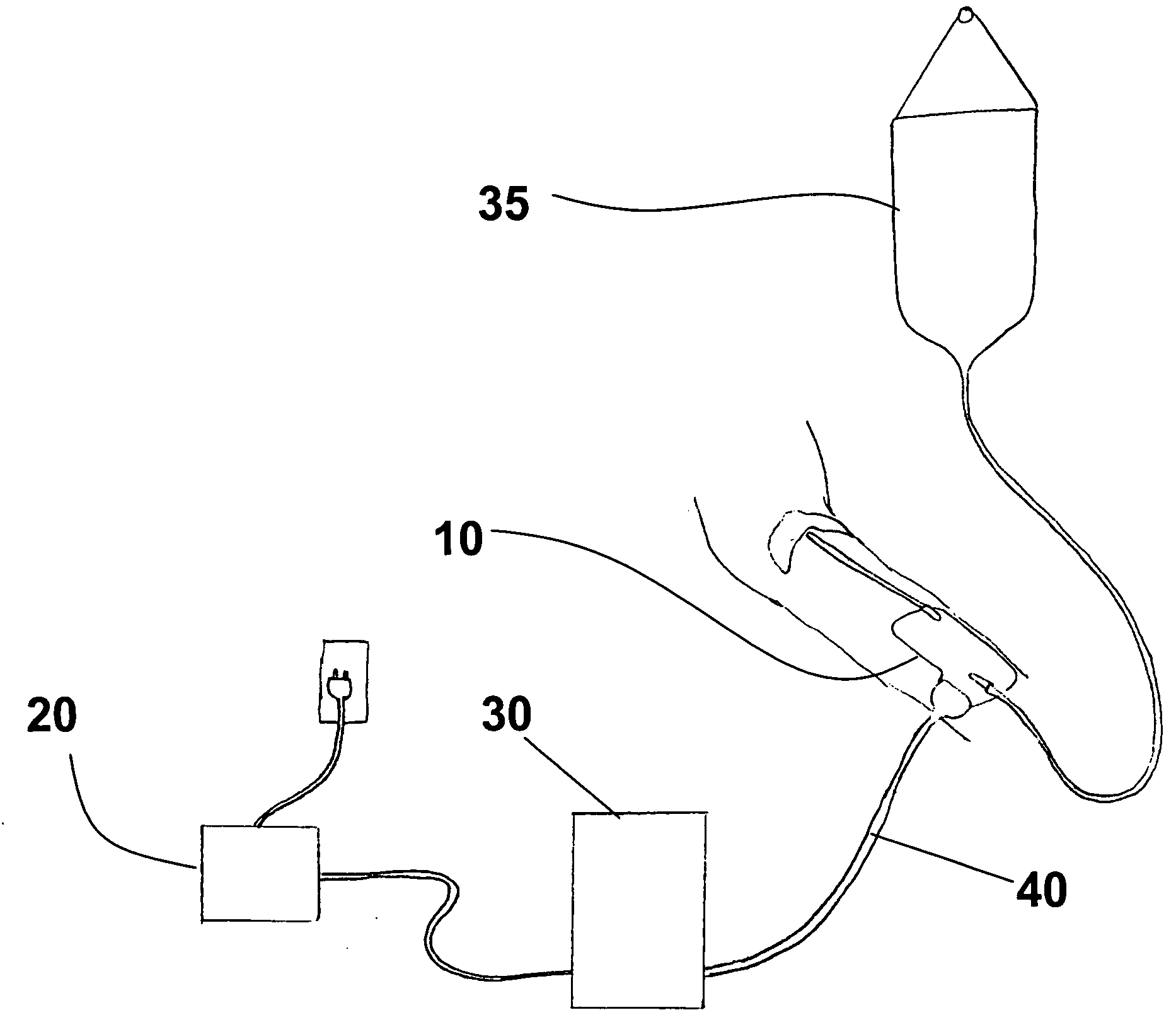
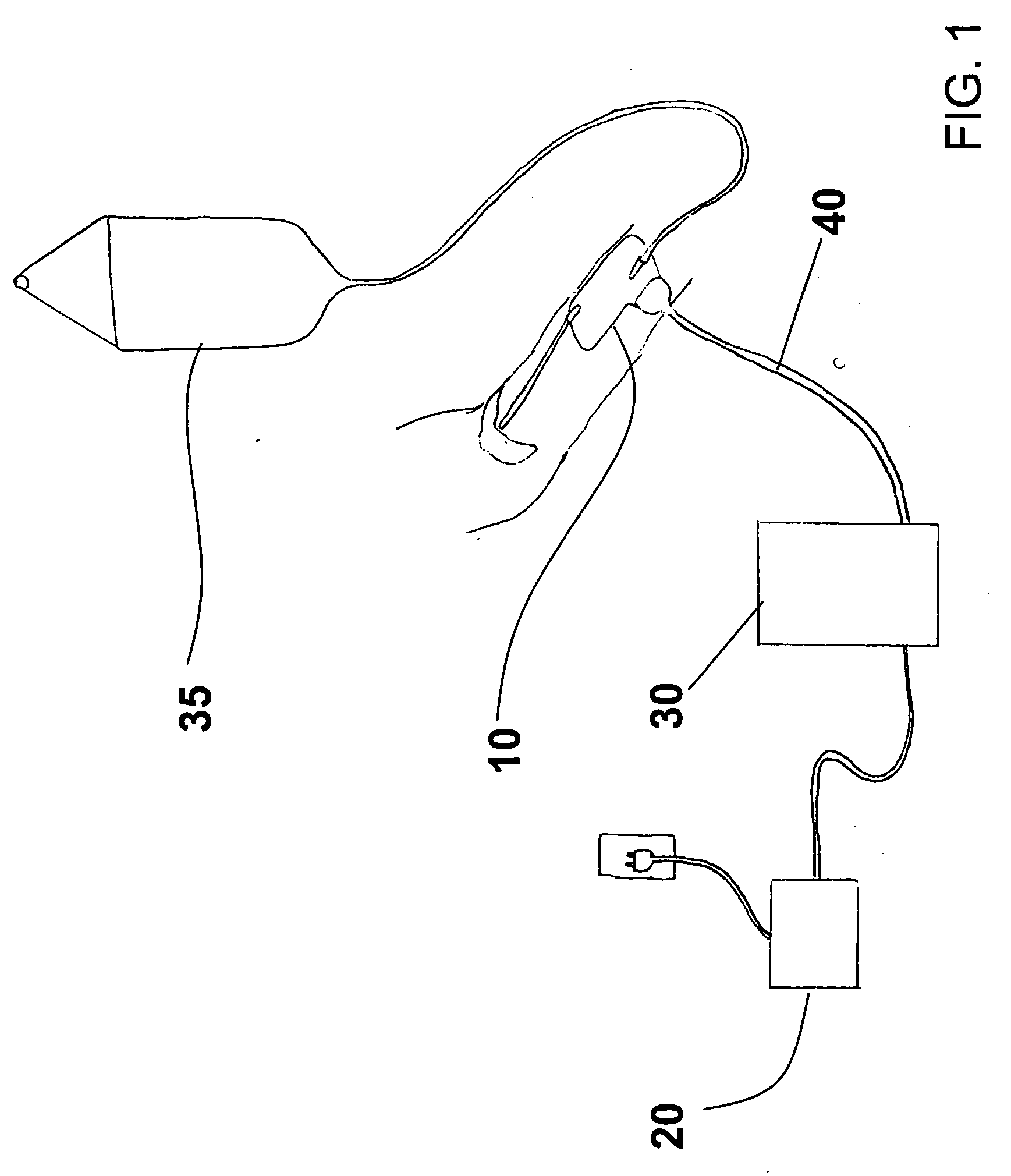
[0012] In embodiments of the present invention, the warming unit includes a connector portion formed on, for example, or otherwise attached to, the laminated heating assembly. The connector portion includes one or more contact points to provide power to the
heating element and to transmit signals with the one or more sensors and / or other features of the unit. The contact points are coupled, for example, to the heating element, to the one or more sensors, and / or to other features via circuit paths formed on the laminated heating assembly or via wires or other couplings. Wires or other couplings connected to the connector portion, in turn couple the warming unit to the controller and / or a power source. In some embodiments, the power source may be attached and detached from the connector portion, allowing flexibility in portability of the warming unit and the use of a variety of power sources (e.g., any power source meeting the power requirements may be connected via the connector portion, so long as suitable connection mechanism is provided). Other features optionally included with the warming unit include a flowrate
measurement device to measure a flowrate of a medium passing through the warming unit or otherwise delivered to a patient.
[0013] In some embodiments, external control circuitry for controlling the temperature of the medium flowing through the warming unit is contained in a controller. Consequently, the circuitry is not susceptible to shorting, smoking, or catching fire, for example, as a result of escaped medium from the heating unit coming into contact with the control circuitry. The warming unit of the present invention thereby provides improved patient and caregiver safety and reliability over prior art warmers having integrated control circuitry.

