Field controlled axial flux permanent magnet electrical machine

a permanent magnet and field control technology, applied in the field of electric machines, can solve the problems of limiting the capability of power electronic drive, reducing the torque capacity of permanent magnets, and increasing the loss and risk of permanent magnet demagnetization, so as to achieve less expensive, less expensive, and easy to implement flux control

Active Publication Date: 2007-03-01
WISCONSIN ALUMNI RES FOUND
View PDF36 Cites 107 Cited by
  • Summary
  • Abstract
  • Description
  • Claims
  • Application Information

AI Technical Summary

Benefits of technology

[0008] Exemplary embodiments of the present invention combine a variable DC coil excitation in addition to permanent magnet excitation. The rotor includes two disks mounted on a common shaft, with each disk carrying magnets and alternate north and south iron poles made of steel. This design modifies the multiple-rotor multiple-stator axial flux permanent magnet machine by adding one or two DC field windings, depending on the machine type, to control the air gap flux and to provide a path for the DC flux through a modification of the rotor structure. As a result, the described field controlled axial flux surface mounted permanent magnet machine provides a less expensive and more readily implemented flux control. The described permanent magnet machine is less expensive because a magnet cost per pound is 10 to 15 times more than the cost of copper or steel.

Problems solved by technology

Conventional permanent magnet machines have a fixed magnetic excitation, which limits the capability of the power electronic drive.
However, these techniques cause large demagnetization current to flow in the machine d-axis, resulting in higher losses and the risk of demagnetization of the permanent magnets.
Such demagnetization can permanently diminish the torque capacity of the machine.
Thus, the attainable speed range is limited by the largest tolerable demagnetization current.
In addition, the capability of the electrical power converters sets an additional limit to the flux weakening range of the permanent magnet machine.
Unfortunately, surface mounted permanent magnet machines, by their nature, lack the capability to control the flux.
As a result, the described field controlled axial flux surface mounted permanent magnet machine provides a less expensive and more readily implemented flux control.

Method used


Image

  • Field controlled axial flux permanent magnet electrical machine
  • Field controlled axial flux permanent magnet electrical machine
  • Field controlled axial flux permanent magnet electrical machine

Examples


Embodiment Construction

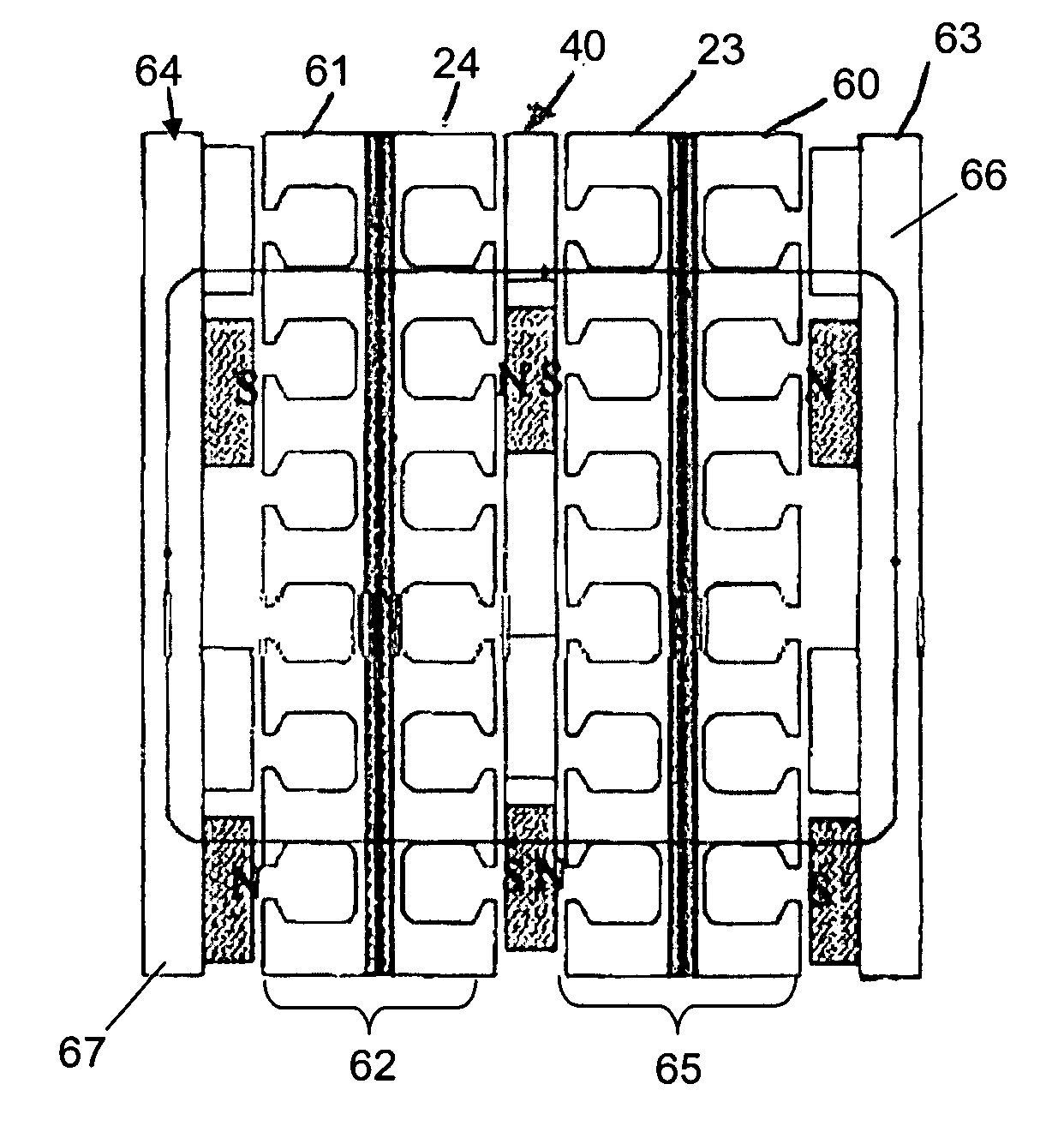
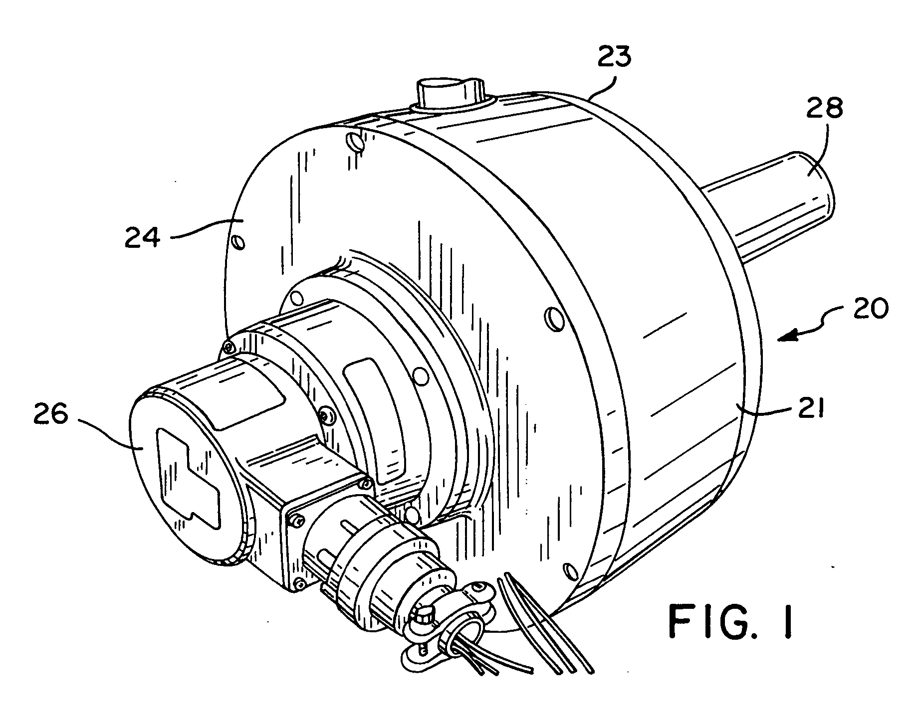
[0026] A field controlled double stator single rotor axial flux internal rotor permanent magnet machine in accordance with the invention is shown in a perspective view at 20 in FIG. 1. The machine 20 has an external casing 21 connected to a first stator section 23 and to a second stator section 24. Three-phase electrical input supplies power to the machine 20 through an external electrical encoder 26 that detects the position and the speed of the machine 20. A central shaft 28 defining a central axis of the machine is available for connection to supply mechanical power to a drive system, e.g., to the wheels of the vehicle.

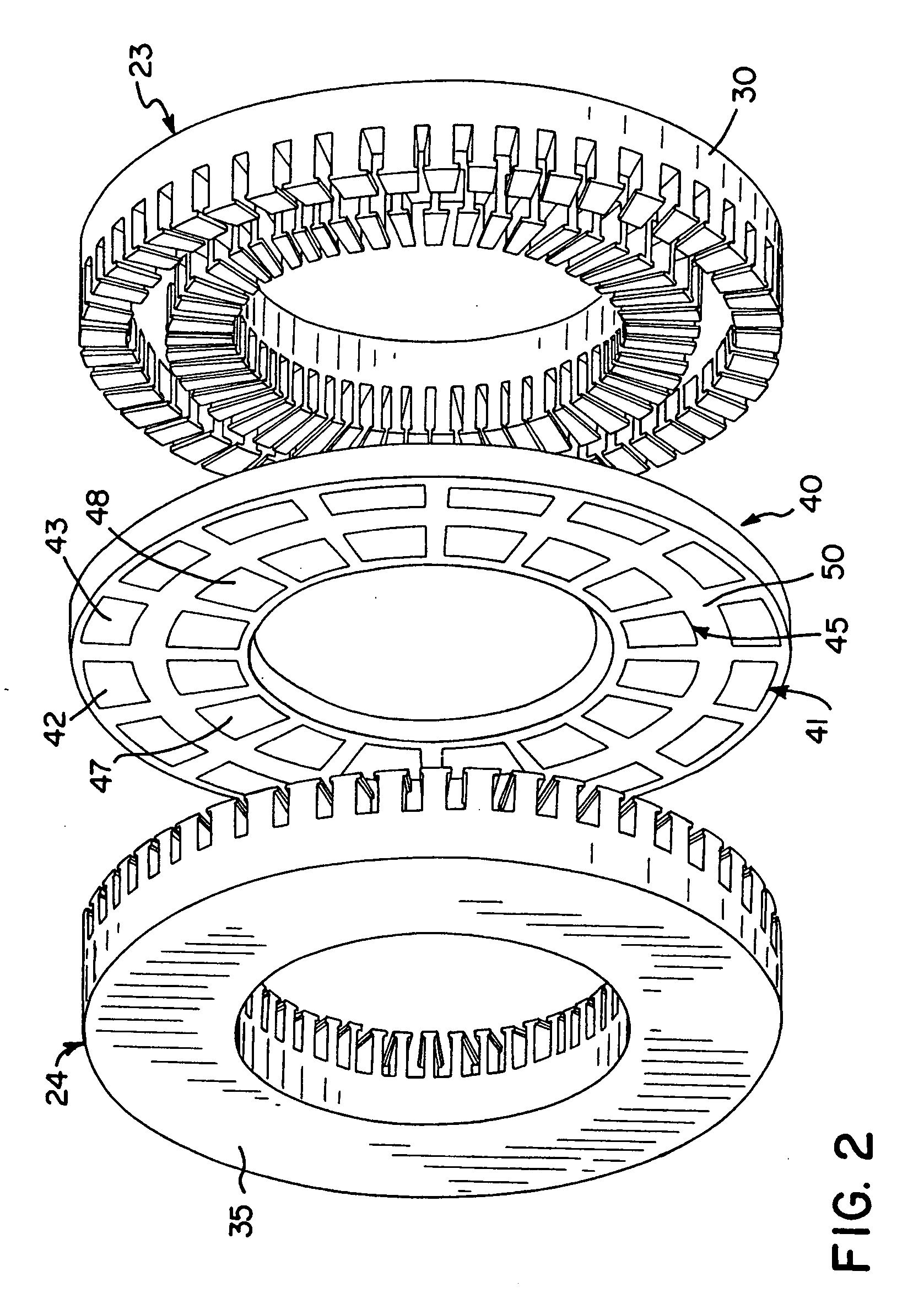
[0027] As illustrated in FIGS. 2 and 3, the first stator 23 includes a ferromagnetic stator frame 30 having slots therein in which is wound an AC drive winding 32 and a DC field coil 33. The second stator 24 has a ferromagnetic frame 35 with slots therein in which is wound an AC coil 36 and a DC field coil 37. The two stators 23 and 24 are mounted in the machine a...


PUM

PropertyMeasurementUnit
magnetic fieldsaaaaaaaaaa
non-magneticaaaaaaaaaa
ferromagneticaaaaaaaaaa

Abstract

An electrical machine is provided. The machine includes at least one rotor mounted for rotation about a central axis and at least two stator sections mounted axially adjacent to and on opposite sides of the rotor. The rotor includes two circumferentially arrayed rows of alternating segments of permanent magnet and ferromagnetic pole pieces. One of the rows is spaced radially inwardly from the other row. The permanent magnet and ferromagnetic pole pieces are separated by a non-ferromagnetic material. The pole pieces are arranged so that the permanent magnet segments in the first row are radially adjacent to ferromagnetic segments in the second row so that the N-S magnetic fields of the permanent magnet segments are aligned axially. Each stator section includes a ferromagnetic stator frame, at least a first AC winding wound in circumferential slots in the stator frame, and a DC field winding wound on the stator frame.

Description

FIELD OF THE INVENTION [0001] This invention pertains generally to the field of electrical machines including motors and generators and particularly to axial air gap permanent magnet machines. BACKGROUND OF THE INVENTION [0002] There is a continuing need for compact, efficient and less expensive electrical machines that have high torque capability over a large speed range and the ability to control machine speed. This need is particularly significant for electrical drives for vehicles, such as hybrid automobiles, which require high torque at zero and low speed, fast acceleration, and preferably regenerative braking. Permanent magnet machines have drawn increasing attention for their potentially greater capability than conventional AC and DC motors to meet these stringent requirements. [0003] The development of permanent magnet technology, such as the availability of more powerful NdFeB magnets, has resulted in increased power and torque density and greater efficiency for permanent m...

Claims


Application Information

Patent Timeline
Patent Type & Authority Applications(United States)
IPC IPC(8): H02K21/12H02K1/22
CPCH02K21/24H02K1/2793H02K1/2796
Inventor AYDIN, METINLIPO, THOMASHUANG, SURONG
Owner WISCONSIN ALUMNI RES FOUND
Why Eureka
Try Eureka