Hybrid-technology metal detector

a metal detector and hybrid technology, applied in the field of metal detectors, can solve the problems of not fully exploiting the opportunities such an approach presents, affecting the use of portable detectors, and affecting the sensitivity of targets, so as to achieve the effect of increasing the sensitivity to targets

Inactive Publication Date: 2007-03-01
DIENCO
View PDF1 Cites 39 Cited by
  • Summary
  • Abstract
  • Description
  • Claims
  • Application Information

AI Technical Summary

Benefits of technology

[0018] It is an object of the present invention to provide a metal detector that includes both pulse-induction and sine-wave technologies in one instrument. It is a further object of the invention to incorporate the best attributes of both systems, without any of their disadvantages.
[0019] A prominent advantage of the combined system is that the reactive and resistive signals captured by the receiver coil are effectively separated, whereby a dynamic ground-balancing system can be implemented, without loss of sensitivity or the accidental “balancing out” of desirable targets, as can occur in conventional sine-wave detectors.
[0020] It is another advantage of the hybrid system that its sensitivity to targets is increased beyond what is possible with either component system by itself. While target signal increases by two orders of magnitude have been observed, the ultimate limit of improvement has not yet been determined.

Problems solved by technology

This procedure is unacceptable in stationary industrial metal detectors and it constitutes a major inconvenience for users of portable detectors.
While Nelson's patent addresses some of the problems inherent in a dual-technology detector, it does not take full advantage of the opportunities such an approach presents.
Unfortunately, this simple expedient allows signals from some desirable targets with short time constants, such as gold nuggets, to also decay to zero before the signal is sampled.
This effect, while erroneously termed “coil overload”, may overdrive the input amplifier of the detector if, it is not designed to have adequate dynamic range.
While touted as means to effect precise adjustment, it is obvious to one skilled in the art that such arrangements are required because the adjustment is very critical.
This is very difficult, if not impossible to accomplish in a sine-wave system.
In such a system, the energy contained in the transmitter coil is largely wasted, since a very small fraction is absorbed by the target.
There are systems that attempt to retrieve some of that energy, but methods such as the one described by Candy in U.S. Pat. No. 5,256,667, prolong the transition to zero, thus decreasing the voltage induced in the target and reducing the detector's sensitivity to small targets.
While target signal increases by two orders of magnitude have been observed, the ultimate limit of improvement has not yet been determined.

Method used


Image

  • Hybrid-technology metal detector
  • Hybrid-technology metal detector
  • Hybrid-technology metal detector

Examples


Embodiment Construction

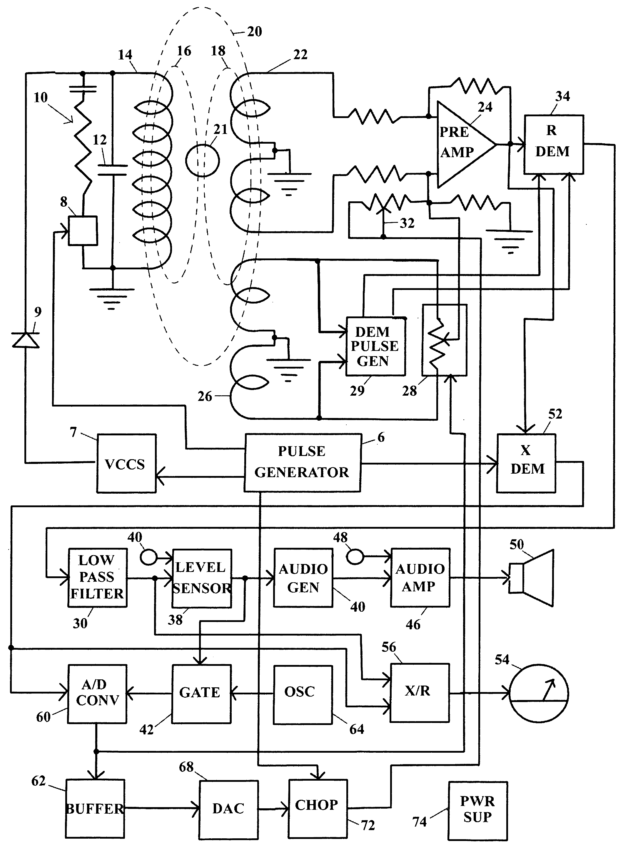
[0026] In FIG. 3, pulse generator 6 sends a linear voltage ramp to voltage-controlled current source 7, which drives transmitter coil 14. The coil is isolated from the current source by “free-wheeling diode”9, which guarantees that the output impedance of the current source is disconnected from the coil, when no current is flowing.

[0027] Capacitor 12 connected across the coil is of a low-loss type that has a low equivalent series resistance, which ensures that the circuit formed with the transmitter coil has a high Q.

[0028] Damping circuit 10 is connected across the transmitter coil at predetermined intervals, by means of switch 8, under the control of pulse generator 6.

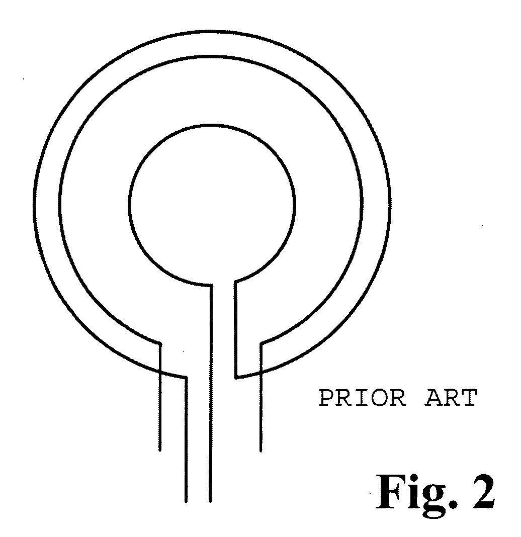
[0029] Receiver coil 22 is of the balanced-induction variety, as shown in FIG. 2, to minimize the magnitude of the voltage generated by direct coupling between the transmitter and receiver coils, as show by magnetic induction lines 20 in FIG. 3.

[0030] Preamplifier 24 amplifies the received signal to a level at wh...


PUM


Abstract

A hybrid-technology metal detector, using pulse-induction and sine-wave excitation of the transmitter coil alternately, in rapid succession. The energy stored in the transmitter coil, in the pulsed mode, is used to shock-excite a high-Q circuit formed by the coil and a parallel capacitor into oscillations in the sine-wave mode. The multiplicative action of the circuit Q causes high currents to flow in the transmitter coil, causing high fluxes to be impressed on the searched area, with increased sensitivity as a result. Using a linear coil-current ramp to assess and minimize the coupling between the transmitter and receiver coils permits effective separation of the reactive and resistive components of the target signals, making accurate identification of targets possible.

Description

[0001] This application claims priority from provisional patent application 60 / 713,420 filed Aug. 31, 2005, which is incorporated herein by reference.BACKGROUND AND THEORY OF THE INVENTION [0002] This invention is related to metal detectors and especially to metal detectors that combine pulse-induction and sine-wave technologies in one instrument. [0003] Metal detectors based on the pulse-induction principle are less affected by ground mineralization than sine-wave detectors. This advantage is counter-balanced by their lower sensitivity to small targets and a lower power-efficiency. The latter necessitates the use of heavy battery packs for portable detectors. [0004] Sine-wave detectors, while capable of high sensitivity, require frequent “re-balancing”, when the soil's or ore's content of magnetic minerals varies. This procedure is unacceptable in stationary industrial metal detectors and it constitutes a major inconvenience for users of portable detectors. [0005] A detector that c...

Claims


Application Information

Patent Timeline
Patent Type & Authority Applications(United States)
IPC IPC(8): G01V3/08
CPCG01V3/105
Inventor WESTERSTEN, ALLAN
Owner DIENCO
Why Eureka
Try Eureka