It has been well known that such EM waves may adversely affect humans, which finally leads many countries across the globe to legislate numerous regulations.
Contrary to rapid advances in those against the EFs and EWs, shielding technologies against the MFs and MWs have not yet been flourished, probably because of the very fact that the Earth itself generates its own MFs and humans have evolved with or lived under the MFs for thousands of years.
Although positive and negative electric charges are very similar to the North and South poles, one major distinction between the
electricity and
magnetism may be that the positive or negative electric charges are easily isolated, while isolation of a single magnetic pole seems impossible.
Because of this, it is impossible to isolate or stop the MFs and MWs.
It is to be understood that, since there is no one-to-one correspondence between electric
conductivity and magnetic permeability, many
electrically conductive substances may turn out to have poor magnetic permeability.
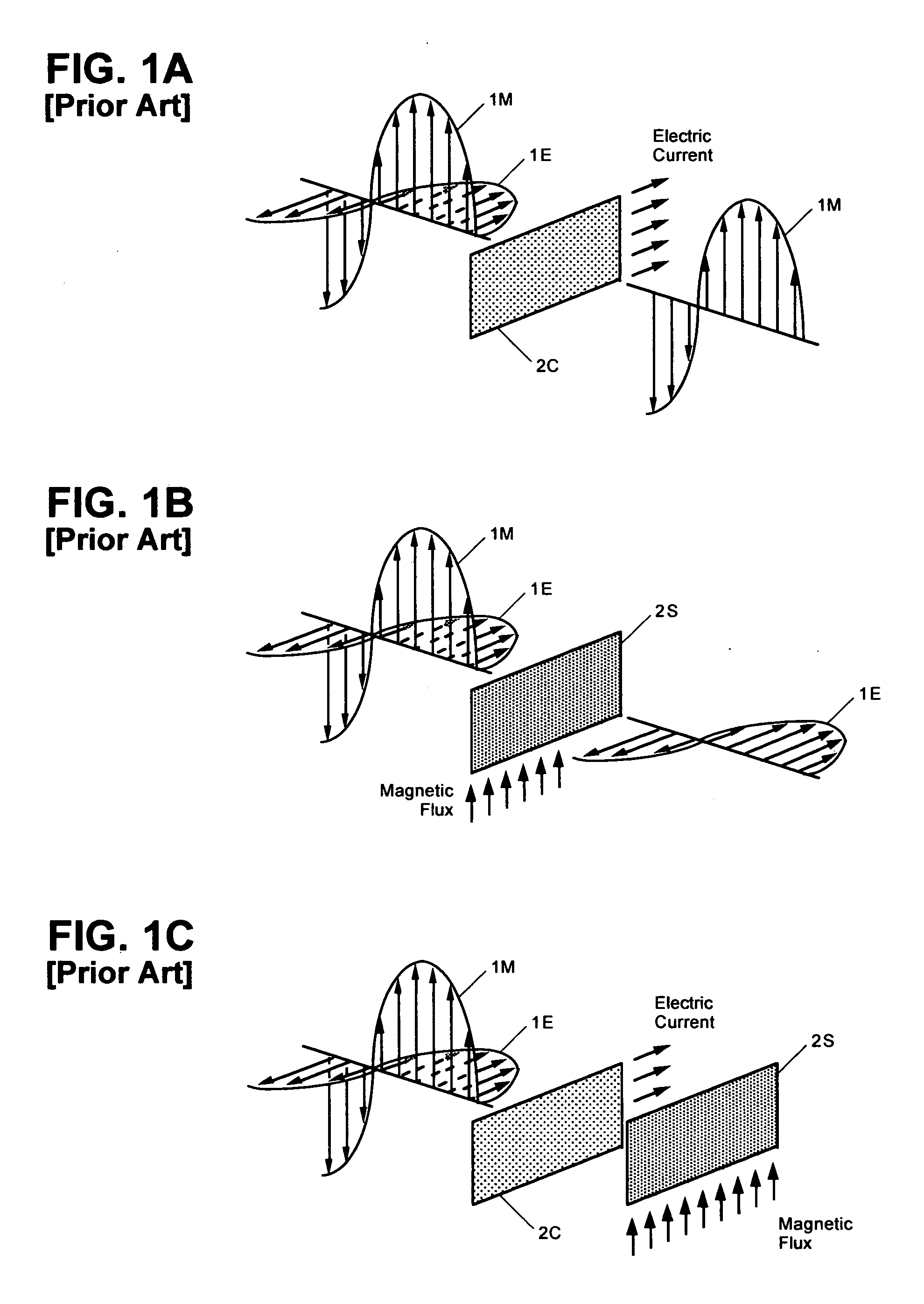
In other words, without reasonable channeling of the MFs and MWs of the EM waves, successful insulation against the EFs and EWs of the EM waves only removes at most one half of the potentially hazardous energy carried by the EM waves.
It is to be understood, however, that such perceptions are totally off the point and very likely to prove wrong, because the Earth's natural
magnetic field is static but the MFs and MWs of the extrinsic EM waves are dynamic or oscillating.
Such induced current may disrupt electrical charge balances of various body fluids,
ion channels, and receptors operating at least partly based on electrical signals.
In addition, the induced current may also degrade or disrupt normal coding and decoding sequences and / or processes of
gene transcriptions, leading to various
gene disorders.
Even if those prior art devices may use a theoretically perfect (and, therefore, practically impossible) electric conductor and a theoretically perfect (practically impossible as well) magnetically permeable shunts, there still are at least a few inherent pitfalls in those prior art approaches.
Without such grounding, however, the EFs and EWs of the EM waves may tend to charge the conductor with opposite polarities during their ascending and descending cycles, where such charges may cancel each other in the long run.
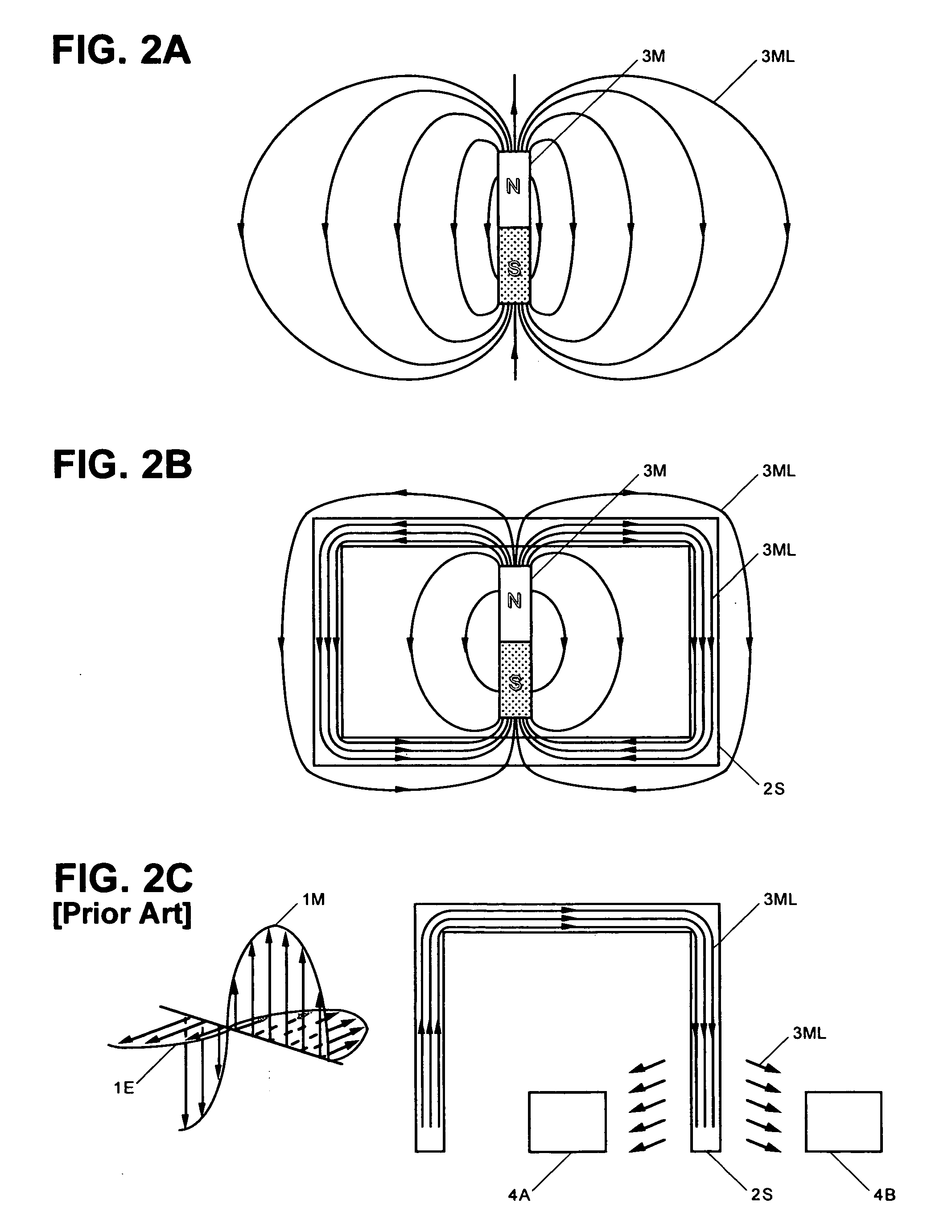
Although the example shown in FIG. 2B appears to be a near perfect solution to shield various targets from the MFs and MWs, it may probably not be applicable to protect a person from the MFs and MWs, unless such a person is to be encircled by and imprisoned inside the shunt indefinitely.
Therefore, such magnetically permeable conventional shunts alone may not be able to protect the target at all.
It is again manifest that all conventional devices and methods for shielding or
shunting the target from the MFs and MWs of the EM waves are ineffective or at best only marginally effective.
like. Although this approach may absorb the MFs and MWs propagating toward the magnet, it suffers from the fact that an entire portion of the target may have to be enclosed and that the magnet gradually loses its magnetic property and sooner or later becomes obs
olete. Therefore, dissipation of the MFs and MWs through the magnetic loss may not be an optimum solution to the p
he EM waves. However, because the induced currents are
out of phase with the extrinsic MFs and MWs by 90°, the Eddy currents may not necessarily cancel the extrinsic
We know that EFs and EWs of the EM waves of
high intensity cause immediate injury to the body.
Such adverse effects have long been corroborated in delicate
electric devices and many devices are now equipped with various means to prevent or at least minimize interference from such EFs and EWs of the EM waves.
However, we have not done much for the MFs and MWs of such EM waves, although the MFs and MWs of the EM waves carry one half of the
total energy thereof.

