Coil device

a coil and ferrite core technology, applied in the direction of transformers/inductance coils/windings/connections, inductances with magnetic cores, inductances, etc., can solve the problems of reducing cost, reducing mechanical strength of terminal portions, and essentially weak against impact, so as to increase heat radiation properties, increase mechanical strength of terminal portions, and ensure sufficient impact resistance and vibration resistance properties

Active Publication Date: 2007-03-01
TDK CORPARATION
View PDF8 Cites 13 Cited by
  • Summary
  • Abstract
  • Description
  • Claims
  • Application Information

AI Technical Summary

Benefits of technology

[0073] (b) It is possible to provide a coil apparatus which can increase mechanical strength of a terminal portion and assure sufficient impact resistant properties and vibration resistant properties even in an application in a severe use environment such as an in-vehicle coil apparatus.
[0074] (f) It is possible to

Problems solved by technology

However, when the divided winding conformation is accepted without providing the flange and a plurality of coil portions are sequentially formed, a winding of a precedently formed coil portion may possibly collapse during formation of a next coil portion.
However, the ferrite core is a brittle sintered body, and essentially weak against impact shocks or vibrations.
Additionally, in not only the in-vehicle coil apparatus but also a coil apparatus which is used as a communication device inductor or a choke coil, a reduction in size, simplification of structure, a decrease in cost and others are always demanded, and hence how these demands are met is also an important problem.
In this prior art, however, it is difficult to meet demands such as a reduction in size, a simplification of structure, a decrease in cost and others.
However, in a coil apparatus in which a core has a square cross-sectional shape, cracks are found in an insulating sheath body in an inspection process in some cases.
However, when a circular cross section which internally touches the original square cross-sectional shape is accepted, a large cross-sectional area of the core cannot be assured, which is not

Method used


Image

  • Coil device
  • Coil device
  • Coil device

Examples


first embodiment

of the Invention>

[0111] A first embodiment of the present invention will now be described hereinafter with reference to the accompanying drawings. It is to be noted that like reference numerals denote the same or corresponding parts in the drawings.

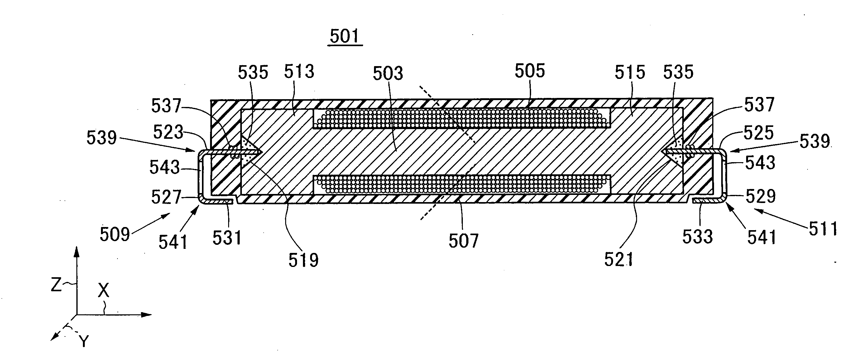
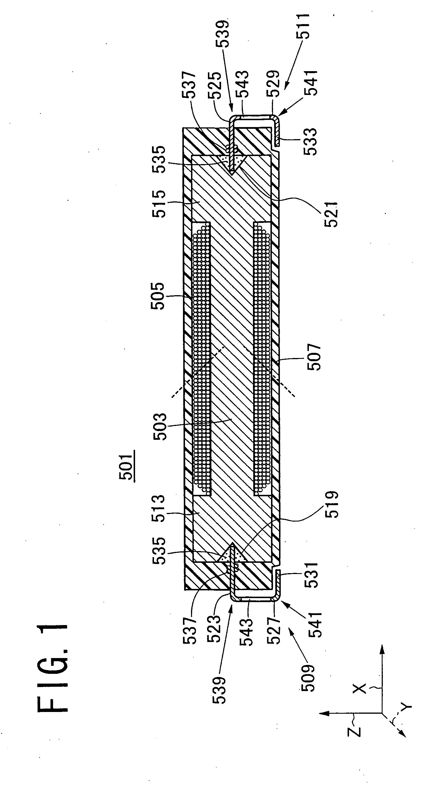
[0112]FIG. 1 shows a vertical cross-sectional view of a coil apparatus according to this embodiment. A coil apparatus 501 mainly comprises a ferrite core 503, a coil 505, an insulating sheath body 507, and a pair of terminals 509 and 511. Further, the coil apparatus 501 is applied to a bi-directional keyless entry system which requires no operation of buttons, an antitheft immobilizer, a tire air pressure monitoring system or the like in, e.g., an automobile.

[0113] The coil 505 is formed of a winding which is wound around an outer peripheral surface of the ferrite core 503 with the ferrite core 503 at the center. The insulating sheath body 507 is provided to cover the entire surfaces of the ferrite core 503 and the coil 505.

[0114] The ...

second embodiment

of the Invention

[0146] A second embodiment of the present invention will now be described hereinafter with reference to the accompanying drawings.

[0147]FIG. 7 is a perspective view of a coil apparatus according to another embodiment of the present invention, FIG. 8 is a front cross-sectional view of the coil apparatus depicted in FIG. 7, and FIG. 9 is a perspective view showing a terminal used in the coil apparatus depicted in FIGS. 7 and 8. This coil apparatus can be used in, e.g., an antenna, an in-vehicle antenna, a transponder, a choke coil, an inductor of an electronic device and others.

[0148] Referring to FIGS. 7 and 8, the coil apparatus includes a core 110, a winding 104 and terminals 151 and 152 and further comprises an insulating resin 107.

[0149] The core 110 has terminal attachment portions 121 and 122 at opposed both ends thereof, and has a winding portion 101 in an intermediate portion thereof. The core 110 is typically a ferrite core, and its material is selected in...

third embodiment

of the Invention

[0182] A third embodiment of the present invention will now be described with reference to the accompanying drawings. It is to be noted that like reference numerals denote like or corresponding parts in the drawings.

[0183]FIG. 18 shows a vertical cross section of a coil apparatus according to a further embodiment of the present invention. A coil apparatus 201 mainly comprises a ferrite core 203, a coil 205, an insulating sheath body 207 and a pair of terminals 209 and 211. Moreover, the coil apparatus 201 is applied to, e.g., a bi-directional keyless entry system which requires no button operation, an antitheft immobilizer, a tire air pressure monitoring system in an automobile.

[0184] The coil 205 is formed of a winding which is wound on an outer peripheral surface of the ferrite core 203 with the ferrite core 203 at the center. The insulating sheath body 207 is provided to cover the entire surfaces of the ferrite core 203 and the coil 205.

[0185] As shown in FIGS....


PUM


Abstract

A coil apparatus having a divided winding conformation and a manufacturing method of the coil apparatus which can prevent a winding from collapsing while achieving a reduction in size of a core and simplification of a structure. A coil apparatus includes a ferrite core and a coil provided around the core. The coil includes at least a first coil portion and a second coil portion, and a boundary end surface of the first coil portion on the second coil portion side is inclined in such a manner that its inner peripheral side is closer to the second coil portion than its outer peripheral side. Further, a boundary end surface of the second coil portion on the first coil portion side is inclined in such a manner that its outer peripheral side is closer to the first coil portion than its inner peripheral side.

Description

TECHNICAL FIELD [0001] The present invention relates to a ferrite core and a coil apparatus using this ferrite core. [0002] A coil apparatus according to the present invention includes an antenna which is applicable to an in-vehicle transponder, or a communication device inductor, a choke coil and others. BACKGROUND ART [0003] Various types of coil apparatuses have been conventionally proposed and come into practical use. As one of such apparatuses, a coil apparatus which can be applied as an in-vehicle antenna or a transponder has been recently proposed. In the coil apparatus which is applied to such an intended purpose, a reduction in size is demanded, and a stable inductance in a working frequency range desired by a customer is also demanded. Therefore, there has been also devised a divided winding conformation in which a coil portion obtained by forming layers of a winding in a radial direction is divided in a direction of an axial center of a core so that divided coil portions ...

Claims


Application Information

Patent Timeline
IPC IPC(8): H01F27/02H01F17/04H01F27/29H01F41/06
CPCH01F17/045H01F27/027H01F41/0633H01F27/33H01F27/292H01F41/082
Inventor YAMASHITA, MITSUHIRONAGASAKA, TAKASHIMIURA, HIDEKIMATSUKAWA, YASUHIROSATO, KAZUOSATO, AKIRASATO, HIRONORIITO, TAKAYUKIKITAJIMA, YASUHIKO
Owner TDK CORPARATION
Why Eureka
Try Eureka