Image processing apparatus and method therefor
a technology of image processing and apparatus, applied in the field of image processing, can solve the problems of reducing the degree of freedom of screen angle, difficult to find a combination to minimize moiré in printing using five or more colors, and rosetta marks are easily generated, so as to reduce the generation of moiré and interference fringes, reduce noise unique to an fm-screen system, and reduce the generation of moiré and rosetta patterns
- Summary
- Abstract
- Description
- Claims
- Application Information
AI Technical Summary
Benefits of technology
Problems solved by technology
Method used
Image
Examples
first embodiment
[Configuration of Image Forming Apparatus]
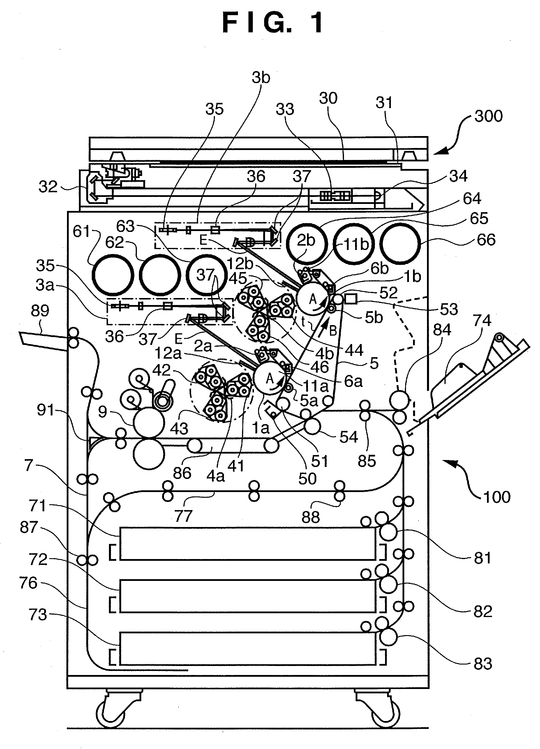
[0036]FIG. 1 is a schematic view showing a full-color image forming apparatus (to be referred to as an “image forming apparatus” hereinafter) according to the embodiment.
[0037] The image forming apparatus has a reader 300 as the upper part and a printer 100 as the lower part. Note that the image forming apparatus may be a multi-functional peripheral equipment having not only a copying function but also a printer function and / or a facsimile function.
[0038] The reader 300 exposes a document 30 set on a glass document table 31 with light from the lamp of a scanner unit 32, and moves the scanner unit 32 in the sub-scanning direction. Light reflected by the document 30 converges on a CCD sensor 34 via the mirror of the scanner unit 32 and a lens 33. Color-separated image signals output from the CCD sensor 34 are amplified by an amplifier circuit (not shown), and converted into R, G, and B image data by a video processing unit (not shown). The ...
second embodiment
[0104] Image processing according to the second embodiment of the present invention will be described below. Note that, in the second embodiment, the same arrangements as in the first embodiment are denoted by the same reference numerals, and a detailed description thereof will be omitted.
[0105]FIG. 14 is a block diagram showing the configuration of an image processing unit 207 of an image forming apparatus according to the second embodiment.
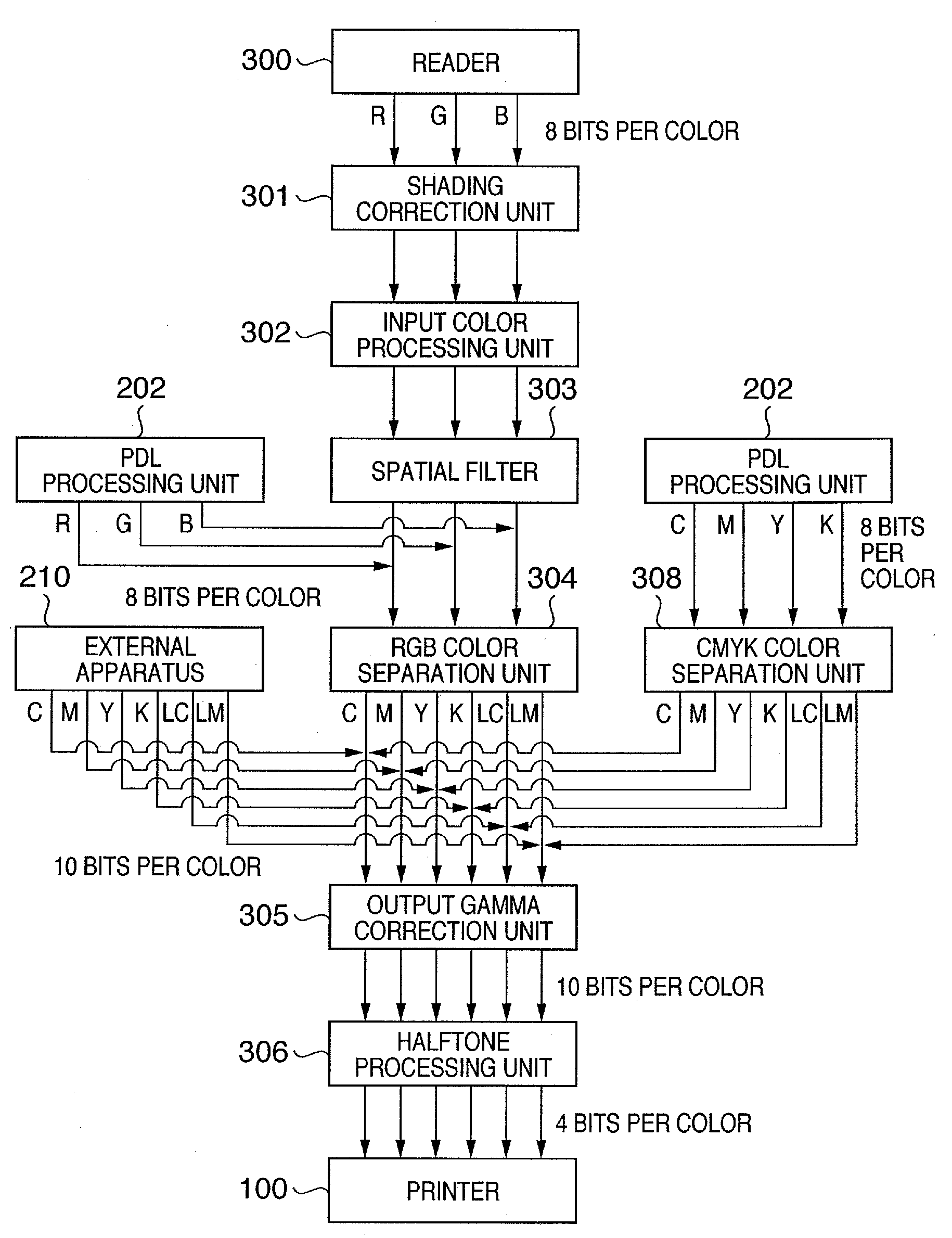
[0106] The image forming apparatus of the second embodiment operates as a system using four colors of cyan, magenta, yellow, and block without using light cyan and light magenta. A halftone processing unit 306 performs digital halftoning to yellow having higher lightness than those of the other three colors by using a dither matrix of a “flat” screen having the same screen angle and the same screen rulings as those for black shown in FIG. 15. For cyan, magenta, and black, a “normal” screen as in the first embodiment will be used. That is, the ...
third embodiment
[0111] Image processing according to the third embodiment of the present invention will be described below. Note that, in the third embodiment, the same arrangements as in the first embodiment are denoted by the same reference numerals, and a detailed description thereof will be omitted.
[0112]FIG. 16 is a block diagram showing the configuration of an image processing unit 207 of an image forming apparatus according to the third embodiment.
[0113] The image forming apparatus of the third embodiment operates as a system using six colors including red (R) and green (G) instead of light cyan and light magenta. An RGB color separation unit 304 separates R, G, and B signals into C, M, Y, and K signals and R and G signals. The CMYK color separation unit 308 separates C, M, Y, and K signals into C, M, Y, and K signals and R and G signals. The halftone processing unit 306 performs digital halftoning to red as a complementary color of cyan by using a dither matrix of a “flat” screen having t...
PUM
 Abstract
Description
Claims
Application Information
 - R&D
- Intellectual Property
- Life Sciences
- Materials
- Tech Scout
- Unparalleled Data Quality
- Higher Quality Content
- 60% Fewer Hallucinations
Browse by: Latest US Patents, China's latest patents, Technical Efficacy Thesaurus, Application Domain, Technology Topic, Popular Technical Reports.
© 2025 PatSnap. All rights reserved.Legal|Privacy policy|Modern Slavery Act Transparency Statement|Sitemap|About US| Contact US: help@patsnap.com


