
Transformerless power conversion circuit for grid-connected power generation systems

a transformerless, grid-connected technology, applied in the direction of electric variable regulation, process and machine control, instruments, etc., can solve the problems of transformer size increase, insufficient electric power, and increased manufacturing cost, so as to improve device size, manufacture cost and conversion efficiency

Active Publication Date: 2007-03-01
IND TECH RES INST
View PDF8 Cites 74 Cited by
  • Summary
  • Abstract
  • Description
  • Claims
  • Application Information

AI Technical Summary

Benefits of technology

[0008] The present invention is intended to provide a transformerless power conversion circuit, wherein transformer is not needed and the DC current problem can be solved. Therefore, the power conversion circuit has significant improvement for device size, manufacture cost and conversion efficiency.

Problems solved by technology

However, the shortage of natural resource and environmental concern for new power plant will make the electrical power more insufficient.
Therefore, the renewable energy generation becomes important issue in industrialized or advanced country.
However, the transformer will increase the size, the cost of the power conversion circuit and reduce conversion efficiency.
However, the transformer will increase the size, weight, cost of the conversion circuit and reduce the conversion efficiency.

Method used


Image

  • Transformerless power conversion circuit for grid-connected power generation systems
  • Transformerless power conversion circuit for grid-connected power generation systems
  • Transformerless power conversion circuit for grid-connected power generation systems

Examples


Embodiment Construction

[0021] The present invention is intended to provide a transformerless conversion circuit, which feeds the electrical power of distributed power generator to the interconnected grid.

[0022]FIG. 9 shows the two-stage three-phase power conversion circuit according to a preferred embodiment of the present invention. The two-stage three-phase power conversion circuit 10 comprises a buck-boost converter 20 and two half-bridge inverters 30. The buck-boost converter 20 converts a DC voltage source to two DC levels and comprises a first active switch Q5, a coupled inductor (first inductor L1 and second inductor L2) sharing the same core, two passive switches (first passive switch D1 and second passive switch D2), and two capacitors (first capacitor C1 and second capacitor C2). The half-bridge inverter 30 converts the two DC levels into alternative voltage for feeding power to grid and comprises four active switches Q1-Q4.

[0023] The active switch Q5 is electrically connected between the posi...


PUM


Abstract

A transformerless power conversion circuit is interconnected with an electric grid and converts an input DC power provided by a power generator into an AC power and feeding the AC power into the grid. The power conversion circuit includes a buck-boost converter converting the input DC power into two sets of DC power levels; and at least one half-bridge inverter converting the two sets of DC power levels into the AC power for feeding into the grid. The isolating transformer can be eliminated and the common ground problem for DC side and AC side is also solved. The power conversion circuit has significant improvement for device size, manufacture cost and conversion efficiency.

Description

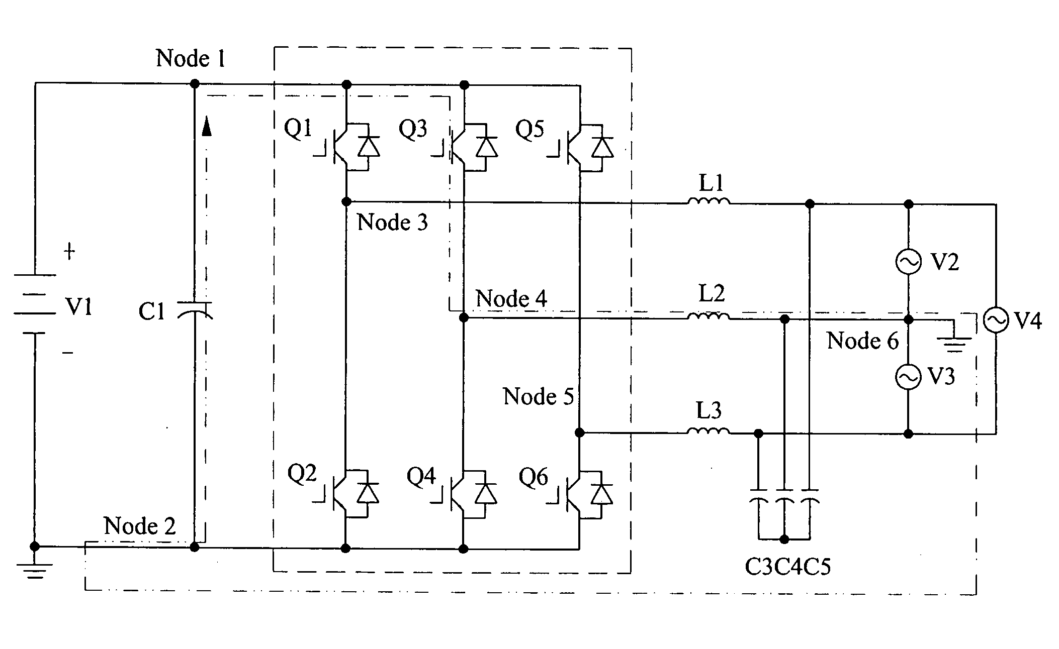
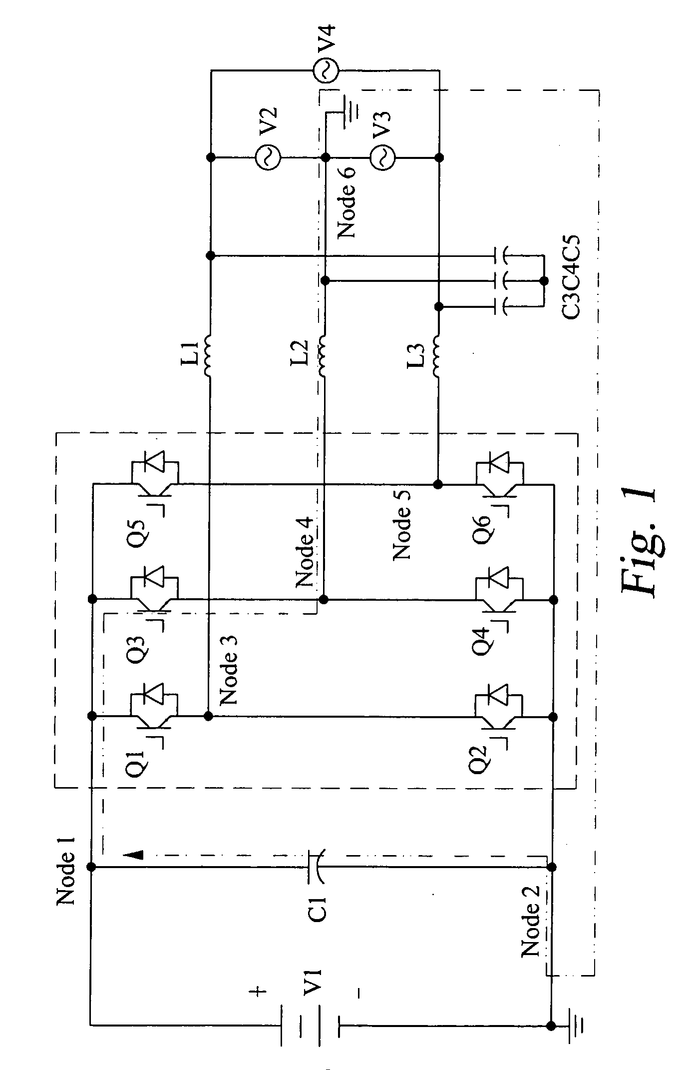
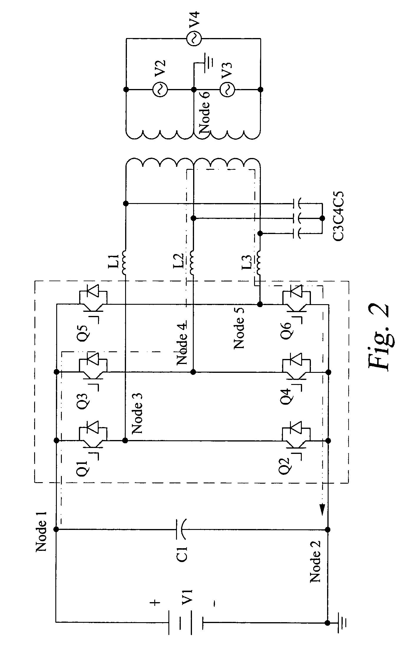
BACKGROUND OF THE INVENTION [0001] 1. Field of the Invention [0002] The present invention relates to a power converter circuit of DC to AC conversion, especially to a conversion circuit, which does not use transformer and transfer the electrical power of distributed energy to electric utility. [0003] 2. Description of Prior Art [0004] The request for electrical power is increased as the industry keeps developing. However, the shortage of natural resource and environmental concern for new power plant will make the electrical power more insufficient. Therefore, the renewable energy generation becomes important issue in industrialized or advanced country. [0005]FIG. 1 shows a prior art single-stage three-phase three-wire power conversion circuit. As shown in this figure, capacitors C1 is parallel to DC power source for filtering noise and stabilizing voltage. In this conversion circuit, if the DC power source has common ground with the ground of public network. When the switch Q3 is tu...

Claims


Application Information

Patent Timeline
IPC IPC(8): H02M7/537
CPCH02J3/38H02M7/5387
Inventor KONISHI, YOSHIHIROLUOR, TAIN-SYHHUANG, YUNG-FU
Owner IND TECH RES INST
Learn More