Laser pulse multiplier

a laser pulse and multiplier technology, applied in the direction of electromagnetic transmission, optical resonator shape and construction, transmission, etc., can solve the problems of limiting the maximum rep rate of a laser with a milliwatt level of peak power to a few kilohertz, unnecessarily wasteing all other laser pulses between macro rf pulses, etc., to improve the electron production rate of the photoinjector and increase the number of electron bunches

Active Publication Date: 2007-03-01
DULY RES
View PDF5 Cites 31 Cited by
  • Summary
  • Abstract
  • Description
  • Claims
  • Application Information

AI Technical Summary

Benefits of technology

[0011] For photoinjector application, increasing the number of laser pulses that illuminate a photocathode in an electron photoinjector produces a plurality of electron bunches and improves the electron production rate in the photoinjector. The present invention increases the number of electron bunches up to several thousand-fold compared with a single bunch photoinjector.

Problems solved by technology

Because of the great disparity between the length of the rf pulse and that of the laser (and consequently electron) pulse, this is a very inefficient way to utilize the energy of the rf pulse.
Current technology limits the maximum rep rate of a laser with a milliwatt level of peak power to a few kilohertz, which is insufficient for the purpose of generating electron bunches typically a few nanoseconds apart for multibunch acceleration.
Furthermore, even if the laser rep rate can be increased to a few hundred megahertz as required, only several thousands of these pulses would be needed during each macro rf pulse, and therefore all other laser pulses between macro rf pulses are unnecessarily wasted.

Method used


Image

  • Laser pulse multiplier
  • Laser pulse multiplier
  • Laser pulse multiplier

Examples


Embodiment Construction

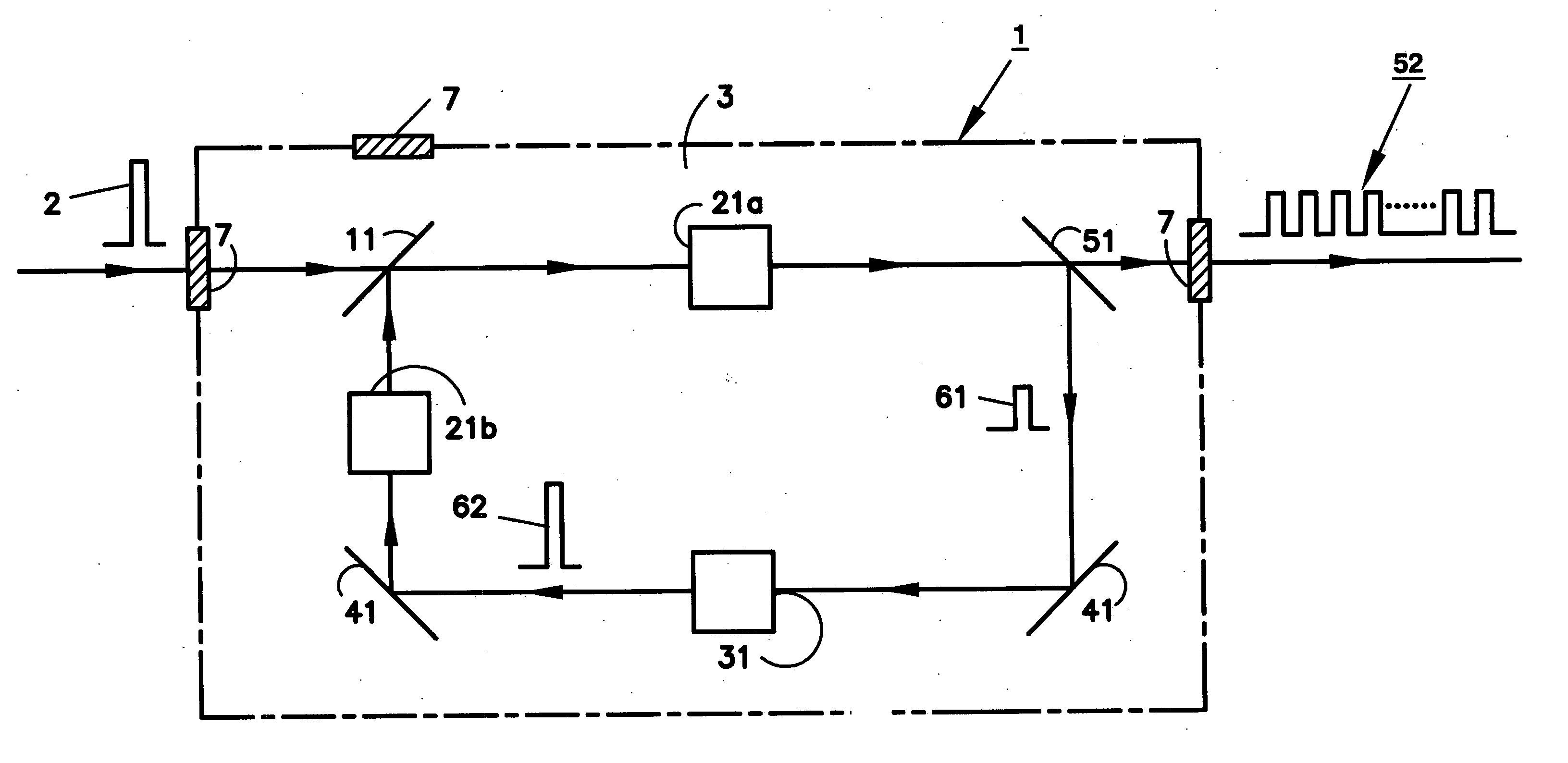
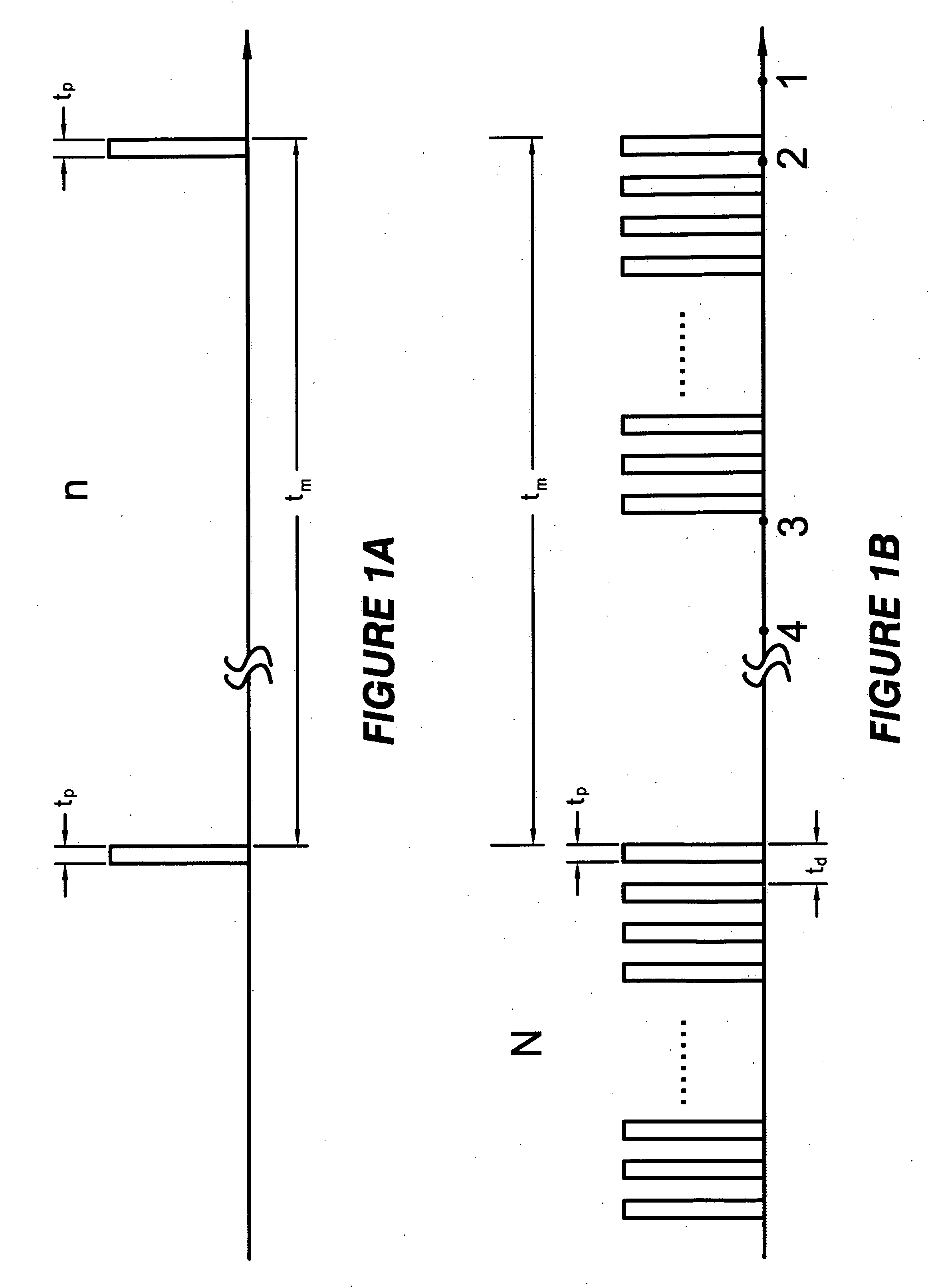
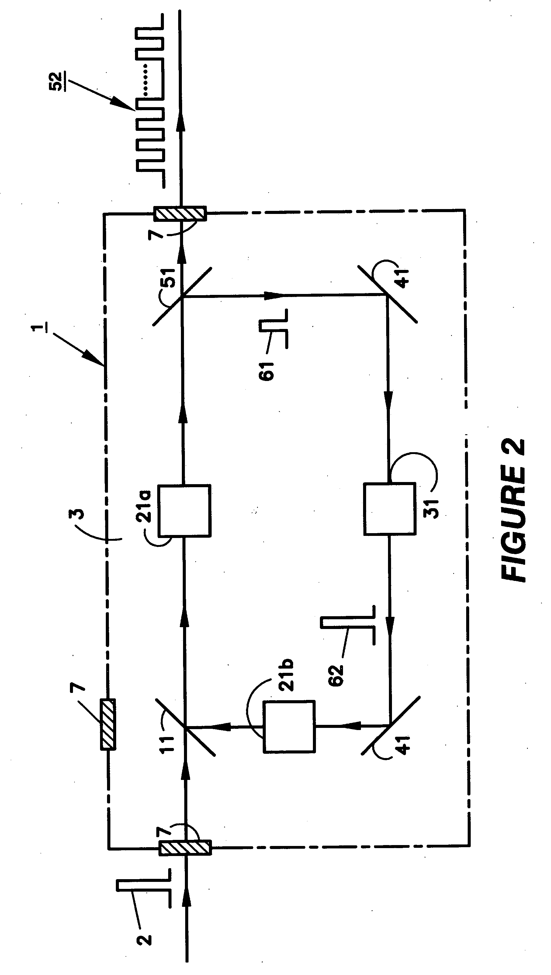
[0018] The time structure of the laser pulses produced by the device in the present invention is illustrated by the following example as shown in FIGS. 1A and 1B. FIG. 1A is a schematic representation of the incoming macro pulse train, comprising a plurality of single pulses with a repetition rate of n times per second, each with a finite duration tp, versus time along the initial beam path at a location just before the first incoming pulse enters the pulse multiplier (PM) 1 of the present invention shown in FIGS. 2 and 3. The time separation between any two adjacent pulses is tm(=1 / n) seconds. FIG. 1B is a schematic representation of the output micro pulse trains along the final beam path at a location just after the pulses leave the PM 1. In this scheme, a train of N output micro laser pulses, with each pulse length tp seconds long and separated by td seconds from its nearest pulse, has the same repetition rate of n times per second as the incoming macro pulse train. If this train...


PUM


Abstract

A device for generating a plurality of laser pulses from a recirculating single laser pulse in an optical delay line that is capable of partially transmitting the trapped pulse out of the delay line. The energy of the partially reflected trapped pulse is restored before beginning another round trip in the delay line. The time structure of an output pulse train thus generated by the device comprises a sequence of macro pulses, each comprising a plurality of micro pulses.

Description

BACKGROUND OF THE INVENTION [0001] 1. Field of the Invention [0002] The present invention is related to the production of a laser pulse train. More specifically, the present invention provides a device that generates a plurality of laser pulses from a single laser pulse using an array of optical elements. [0003] 2. Description of Prior Art [0004] For many applications, a high-yield electron source with excellent beam quality is needed. For example, short pulse, nearly mono-energetic, tunable x-rays may be generated by the collision of a plurality of electron bunches from a photoinjector with synchronized photon pulses in a high-power laser beam via Compton backscattering. Such x-rays have uses in medical imaging, crystallography, and designer drugs, to name a few. In addition to x-ray generation via Compton scattering, the laser pulses may be used directly or in another manner as described above in other applications such as in optical communications. Another use of a laser-triggere...

Claims


Application Information

Patent Timeline
Patent Type & Authority Applications(United States)
IPC IPC(8): H01S3/10H01S3/08
CPCH01S3/235H01S3/107
Inventor YU, DAVID U. L.
Owner DULY RES
Why Eureka
Try Eureka